


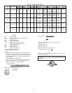

fuse/circuit breaker size and minimum circuit amps (ampacity) for
wire sizing. See Table 3 for electrical data.
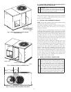
The field-supplied disconnect may be mounted on the unit over the
high-voltage inlet hole. (See Fig. 2-4.)
CAUTION: Operation of unit on improper line voltage
constitutes abuse and may cause unit damage that could
affect warranty.
B. ROUTING POWER LEADS INTO UNIT
Use only copper wire between disconnect and unit. The high-
voltage leads should be in a conduit until they enter the unit;
conduit termination at the unit must be watertight. Run the
high-voltage leads through the hole on the control box side of the
unit (see Fig. 10 for location). When the leads are inside the unit,
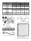
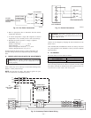
run leads to the control box (Fig. 11). On 3-phase units, connect
the leads to the black, yellow, and blue wires (see Fig. 12).
C. CONNECTING GROUND LEAD TO UNIT GROUND
Refer to Fig. 11 and 12. Connect the ground lead to the chassis
using the unit ground lug in the control box.
D. ROUTING CONTROL POWER WIRES
Form a drip-loop with the thermostat leads before routing them
into the unit. Route the thermostat leads through grommeted hole
provided in unit (see Fig. 10) into unit control box. Connect
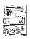
thermostat leads to unit control power leads as shown in Fig. 13.
Route thermostat wires through grommet providing a drip-loop at
the panel. Connect low-voltage leads to the thermostat as shown in
Fig. 13.
The unit transformer supplies 24-v power for complete system
including accessory electrical heater. Transformer is factory wired
for 230-v operation. If supply voltage is 208 v, rewire transformer
primary as described in the Special Procedures for 208-v Opera-
tion section below.
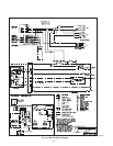
E. ACCESSORY ELECTRIC HEAT WIRING
Refer to accessory electric heat installation instructions for infor-
mation on installing accessory electric heat. Accessory electric
heat wiring is shown in Fig. 14.
F. SPECIAL PROCEDURES FOR 208-V OPERATION
WARNING: Make sure that the power supply to the unit
is switched OFF before making any wiring changes.
Electrical shock can cause serious injury or death.
1. Remove wirenut from connection of ORG wire to BLK
wire. Disconnect the ORG transformer-primary lead from
the BLK wire. Save wirenut. See unit wiring label. (See Fig.
15.)
2. Remove the wirenut from the terminal on the end of the
RED transformer-primary lead.
3. Save the wirenut.
4. Connect the RED lead to the BLK wire from which the
ORG lead was disconnected. Insulate with wirenut from
Step 1.
5. Using the wirenut removed from the RED lead, insulate the
loose terminal on the ORG lead.
6. Wrap the wirenuts with electrical tape so that the metal
terminals cannot be seen.
Indoor blower-motor speeds may need to be changed for 208-v
operation. Refer to Indoor Airflow and Airflow Adjustments
section in this publication.
PRE-START-UP
WARNING: Failure to observe the following warnings
could result in serious injury or death:
1. Follow recognized safety practices and wear protective
goggles when checking or servicing refrigerant system.
2. Do not operate compressor or provide any electric
power to unit unless compressor terminal cover is in
place and secured.
3. Do not remove compressor terminal cover until all
electrical sources are disconnected.
4. Relieve all pressure from both high and low pressure
sides of the system before touching or disturbing
anything inside terminal box if refrigerant leak is
suspected around compressor terminals. Use accepted
methods to recover refrigerant.
5. Never attempt to repair soldered connection while
refrigerant system is under pressure.
6. Do not use torch to remove any component. System
contains oil and refrigerant under pressure. To remove
a component, wear protective goggles and proceed as
follows:
a. Shut off electrical power to unit.
b. Relieve all refrigerant from system using both high-
and low-pressure ports. Use accepted methods to
recover refrigerant.
c. Cut component connecting tubing with tubing cutter
and remove component from unit.
d. Carefully unsweat remaining tubing stubs when
necessary. Oil can ignite when exposed to torch
flame.
Use the Start-Up Checklist supplied at the end of this book
and proceed as follows to inspect and prepare the unit for
initial start-up:
1. Remove all access panels.
2. Read and follow instructions on all DANGER, WARNING,
CAUTION, and INFORMATION labels attached to, or
shipped with, unit.
Make the following inspections:
a. Inspect for shipping and handling damages such as
broken lines, loose parts, disconnected wires, etc.
b. Inspect for oil at all refrigerant tubing connections and
on unit base. Detecting oil generally indicates a refrig-
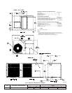
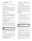
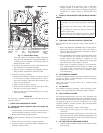
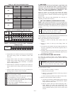
Fig. 10—Unit Electrical Connection Entry Holes
C00010
HIGH-VOLTAGE
POWER WIRING
ENTRY HOLE
LOW-VOLTAGE
WIRING ENTRY
HOLE
—8—