


2. Refer to appropriate chart to determine what the suction
temperature should be.
3. If suction temperature is high, add refrigerant. If suction
temperature is low, carefully recover some of the charge.
4. Recheck the suction pressure as charge is adjusted.
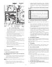
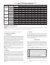
EXAMPLE: (Fig. 17)
Outdoor Temperature .....................85° F
Suction Pressure .......................80 psig
Suction Temperature should be .............70° F
(Suction Temperature may vary ±5˚ F.)
If Chargemaster® charging device is used, temperature and
pressure readings must be accomplished using the charging
chart.
IV. INDOOR AIRFLOW AND AIRFLOW ADJUSTMENTS
CAUTION: For cooling operation, the recommended
airflow is 350 to 450 cfm per each 12,000 Btuh of rated
cooling capacity.
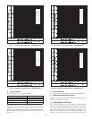
Table 4 shows dry coil air delivery for horizontal discharge units.
Tables 5-7 show pressure drops.
NOTE: Be sure that all supply- and return-air grilles are open,
free from obstructions, and adjusted properly.
WARNING: Disconnect electrical power to the unit
before changing blower speed. Electrical shock can cause
serious injury or death.
Airflow can be changed by changing the lead connections of the
blower motor.
Units 564A036,048, and 060 blower motors are factory wired for
low speed operation. Unit 564A042 is factory wired for medium
speed operation.
A. For 208/230-v
The motor leads are color-coded as follows:
3-SPEED 2-SPEED
black = high speed black = high speed
blue = medium speed -
red = low speed red = low speed
To change the speed of the blower motor (BM), remove the fan
motor speed leg lead from the indoor (evaporator) fan relay (IFR)
and replace with lead for desired blower motor speed. Insulate the
removed lead to avoid contact with chassis parts.
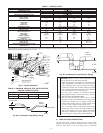
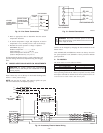
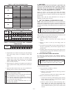
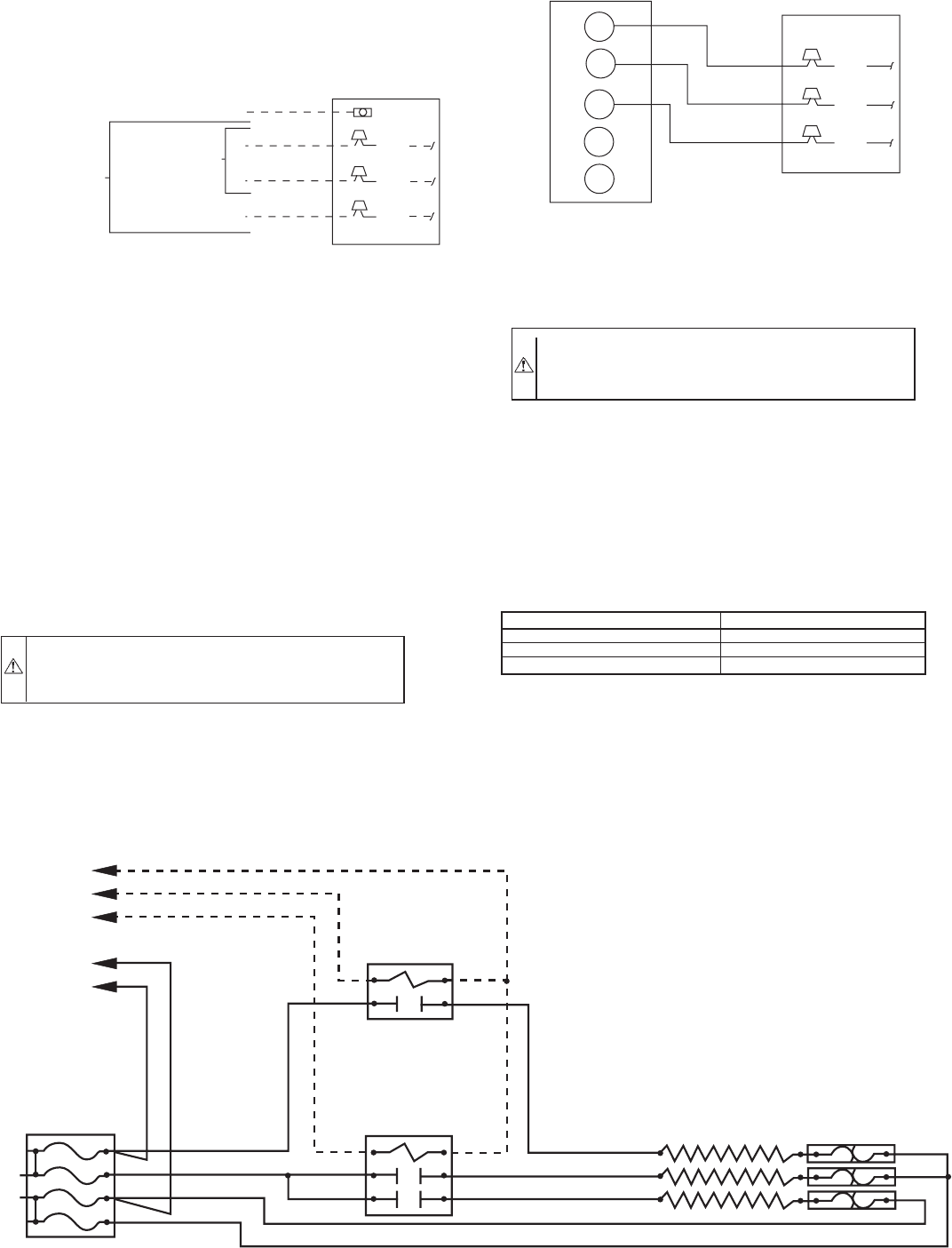
Fig. 12—Line Power Connections
C00012
3-PHASE
CONNECTIONS
TO DISCONNECT
PER NEC
SINGLE-PHASE
CONNECTIONS
TO DISCONNECT
PER NEC
GROUND
LEAD
UNIT GROUND
BLK
YEL
BLU
L
L
L
Fig. 13—Control Connections
C00013
R
G
Y
W1
W2
RED
GRN
YEL
UNIT CONTROL BOX
THERMOSTAT
AND SUBBASE
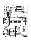
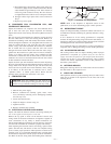
Fig. 14—Accessory Electric Heater Wiring
C00014
C
W1
W1
TO
UNIT POWER
WIRING
BLK
YEL
BRN (COMMON)
VIO (STEP 2)
WHT ( STEP 1)
CONTACTOR 2
YEL
BRN
YEL
CONTACTOR 1
YEL
YEL
BRN
YEL
YEL
FUSE BLOCK
L2
L1
YEL
YEL
BLK
BLK
F3
F4
F1
F2
EL 1
EL 2
EL 3
BLK
BLK
BLK
AUTO-LIMIT
—10—