


c. Reassemble blower into housing. Place upper orifice ring
on blower to judge location of the blower wheel. Blower
wheel should be approximately 0.2-in. below bottom of
orifice ring when centered correctly. Be sure setscrews
are tightened on motor and are not on round part of shaft.
d. Set upper orifice ring in place with 3 screws removed in
Step 1.
e. Replace top access panel.
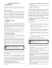
IV. CONDENSER COIL, EVAPORATOR COIL, AND
CONDENSATE DRAIN PAN
Inspect the condenser coil, evaporator coil, and condensate drain
pan at least once each year. Proper inspection and cleaning
requires the removal of the unit top. See Unit Top Removal section
above.
The coils are easily cleaned when dry; therefore, inspect and clean
the coils either before or after each cooling season. Remove all
obstructions (including weeds and shrubs) that interfere with the
airflow through the condenser coil. Straighten bent fins with a fin
comb. If coated with dirt or lint, clean the coils with a vacuum
cleaner, using a soft brush attachment. Be careful not to bend the
fins. If coated with oil or grease, clean the coils with a mild
detergent-and-water solution. Rinse coils with clear water, using a
garden hose. Be careful not to splash water on motors, insulation,
wiring, or air filter(s). For best results, spray condenser-coil fins
from inside to outside the unit. On units with an outer and inner
condenser coil, be sure to clean between the coils. Be sure to flush
all dirt and debris from the unit base.
Inspect the drain pan and condensate drain line when inspecting
the coils. Clean the drain pan and condensate drain by removing all
foreign matter from the pan. Flush the pan and drain tube with
clear water. Do not splash water on the insulation, motor, wiring,
or air filter(s). If the drain tube is restricted, clear it with a
‘‘plumbers snake’’ or similar probe device. Ensure that the
auxiliary drain port above the drain tube is also clear.
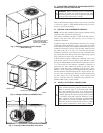
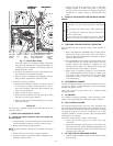
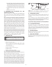
V. CONDENSER FAN
CAUTION: Keep the condenser fan free from all ob-
structions to ensure proper cooling operation. Never place
articles on top of the unit. Damage to unit may result.
1. Shut off unit power supply.
2. Remove condenser-fan assembly (grille, motor, motor
cover, and fan) by removing screws and flipping assembly
onto unit top cover.
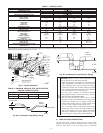
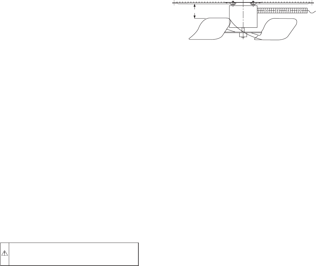
3. Loosen fan hub setscrews.
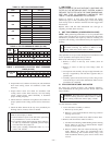
4. Adjust fan height as shown in Fig. 21.
5. Tighten setscrews.
6. Replace condenser-fan assembly.
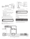
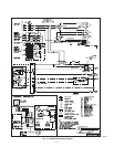
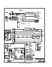
VI. ELECTRICAL CONTROLS AND WIRING
Inspect and check the electrical controls and wiring annually. Be
sure to turn off the electrical power to the unit.
Remove the top panel to locate all the electrical controls and
wiring. Check all electrical connections for tightness. Tighten all
screw connections. If any smoky or burned connections are
noticed, disassemble the connection, clean all the parts, restrip the
wire end and reassemble the connection properly and securely.
After inspecting the electrical controls and wiring, replace all the
panels. Start the unit, and observe at least one complete cooling
cycle to ensure proper operation. If discrepancies are observed in
operating cycle, or if a suspected malfunction has occurred, check
each electrical component with the proper electrical instrumenta-
tion. Refer to the unit wiring label when making these checkouts.
NOTE: Refer to the Sequence of Operation section in this
publication, as an aid in determining proper control operation.
VII. REFRIGERANT CIRCUIT
Inspect all refrigerant tubing connections and the unit base for oil
accumulations annually. Detecting oil generally indicates a refrig-
erant leak.
If oil is detected or if low cooling performance is suspected,
leak-test all refrigerant tubing using an electronic leak-detector, or
liquid-soap solution. If a refrigerant leak is detected, refer to Check
for Refrigerant Leaks section in this publication.
If no refrigerant leaks are found and low cooling performance is
suspected, refer to Refrigerant Charge section in this publication.
VIII. EVAPORATOR AIRFLOW
The cooling airflow does not require checking unless improper
performance is suspected. If a problem exists, be sure that all
supply- and return-air grilles are open and free from obstructions,
and that the air filter is clean. When necessary, refer to Indoor
Airflow and Airflow Adjustments section in this publication to
check the system airflow.
IX. METERING DEVICES
Refrigerant metering devices are fixed orifices and are located in
the inlet header to the evaporator coil.
X. LIQUID LINE STRAINER
The liquid line strainer (to protect metering device) is made of wire
mesh and is located in the liquid line on the inlet side of the
metering device.
Fig. 21—Condenser-Fan Adjustment
C00021
3.125 in.
—17—