


CAUTION: Failure to follow these precautions could
result in damage to the unit being installed:
1. Make all electrical connections in accordance with
NEC ANSI/NFPA (latest edition) and local electrical
codes governing such wiring. In Canada, all electrical
connections must be in accordance with CSA standard
C22.1 Canadian Electrical Code Part 1 and applicable
local codes. Refer to unit wiring diagram.
2. Use only copper conductor for connections between
field-supplied electrical disconnect switch and unit.
DO NOT USE ALUMINUM WIRE.
3. Be sure that high-voltage power to unit is within
operating voltage range indicated on unit rating plate.
4. Insulate low-voltage wires for highest voltage con-
tained within conduit when low-voltage control wires
are run in same conduit as high-voltage wires.
5. Do not damage internal components when drilling
through any panel to mount electrical hardware, con-
duit, etc. On 3-phase units, ensure phases are balanced
within 2%. Consult local power company for correc-
tion of improper voltage and/or phase imbalance.
A. HIGH-VOLTAGE CONNECTIONS
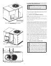
The unit must have a separate electrical service with a field-
supplied, waterproof disconnect switch mounted at, or within sight
from, the unit. Refer to the unit rating plate for maximum
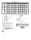
TABLE 1—PHYSICAL DATA
UNIT 564A 036 042 048 060
OPERATING WEIGHT (lbs) 250 297 310 350
COMPRESSOR TYPE Reciprocating
REFRIGERANT Charge (lb)
R-22
4.7 4.4 6.1 7.5
REFRIGERANT METERING DEVICE Acutrol™ Device
CONDENSER COIL
Rows...Fins/in.
Face Area (sq ft)
Copper Tubes, Aluminum Plate Fins
2...17
6.2
1...17
11.1
2...17
8.6
2...17
10.7
CONDENSER-FAN MOTOR CFM
Nominal Rpm
Motor Hp
Diameter (in.)
2000
1100
1/4
20
2600
1100
1/4
20
2600
1100
1/4
20
2800
1100
1/4
20
EVAPORATOR COIL Copper Tubes, Aluminum Plate Fins
Rows...Fins/in.
Face Area (sq ft)
3...15
3.1
3...15
3.9
3...15
4.3
4...15
4.9
EVAPORATOR FAN MOTOR
Blower Motor Size (in.)
Nominal Cfm
Rpm Range
Number of Speeds
Factory Speed Setting
Motor Hp
Direct Drive
10x8
1200
800-1050
3
Low
1/2
10x9
1400
800-1050
3
Med
1/2
10x9
1600
1000-1100
2
Low
3/4
10x10
1850
950-1100
3*, 2*
Low
1
CONNECTING DUCT SIZES
Supply Air (in.)
Return Air (in.)
Round
14
14
Square
13.9 x 13.9
13.9 x 27.8
FIELD-SUPPLIED RETURN-AIR FILTER†
Throwaway (in.)
24 x 24 24 x 24 24 x 30 24x30
* 460-v motors are 2-speed or 3-speed.
†Required filter sizes shown are based on the ARI (Air Cinditioning and Refrigeration Institute) rated airflow at a velocity of 300 ft/min for throwaway type or 450 ft/min for
high capacity type. Recommended filters are 1-in. thick.
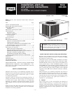
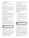
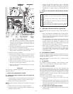
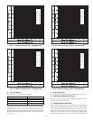
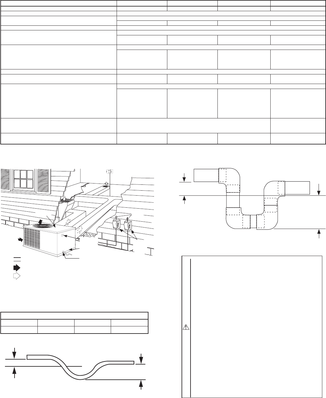
Fig. 8—Typical Installation
C00008
C00008
TOP COVER
INDOOR
THERMOSTAT
DISCONNECT
PER NEC*
(UNIT AND
ELECTRIC
HEATER)
FROM
POWER
SOURCE
RETURN
AIR
POWER AND
LOW-VOLTAGE
ENTRY
COMPOSITE
RUST-PROOF
BASEPAN
CONDENSATE
DRAIN
CONNECTION
*Separate disconnect per NEC
(National Electrical Code) required
for electric heater when single-
point conection is not used.
Power Wiring
Control Wiring
Condenser Airflow
Evaporator Airflow
TABLE 2—MINIMUM AIRFLOW FOR SAFE ELECTRIC
HEATER OPERATION (CFM)
SIZE
036 042 048 060
1200 1225 1400 1750
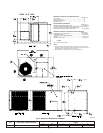
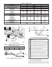
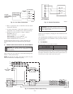
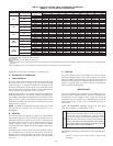
Fig. 9A—Condensate Trap (Using Tubing)
C99013
1” (25mm) MIN.
2” (50mm) MIN.
TRAP
OUTLET
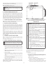
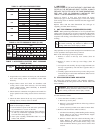
Fig. 9B—Condensate Trap (Using PVC Piping)
C00009
TRAP
OUTLET
2" min.
1" min.
—7—