


through the overload with an ohmmeter or continuity tester.
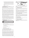
VI. SEQUENCE OF OPERATION
A. FAN OPERATION
The FAN switch on the thermostat controls indoor fan operation.
When the FAN switch is placed in the ON position, the IFR
(indoor-fan relay) is energized through the G terminal on the
thermostat. The normally-open contacts close, which then provide
power to the indoor (evaporator) fan motor (IFM). The IFM will
run continuously when the FAN switch is set to ON.
When the FAN switch is set to AUTO, the thermostat deenergizes
the IFR (provided there is not a call for cooling). The contacts open
and the IFM is deenergized. The IFM will be energized only when
there is a call for cooling, or if the unit is equipped with accessory
electric heat, the indoor-fan motor will also run while he accessory
electric heat is energized.
NOTE: 564A060 unit is equipped with a time-delay relay. On this
unit, the indoor fan remains on for 30 seconds after G or Y is
deenergized.
B. COOLING
On a call for cooling, the compressor contactor (C) and the IFR are
energized through the Y and G terminals of the thermostat. On
units with a compressor time-delay relay, there is a 5-minute (± 45
sec) delay between compressor starts. Energizing the compressor
contactor supplies power to the compressor and the outdoor
(condenser) fan motor (OFM). Energizing the IFR provides power
to the IFM.
When the need for cooling has been satisfied, the OFM, compres-
sor, and IFM (FAN on AUTO) are deenergized. If the unit is
equipped with a 30-second delay, the indoor fan will remain
energized for 30 seconds after the compressor is deenergized 060
unit only).
C. HEATING
If accessory electric heaters are installed, on a call for heat the
thermostat energized the W relay which energizes the electric
heaters. The IFR is energized which starts the indoor-fan motor. If
the heaters are staged, W2 is energized when the second stage of
heating is required. When the need for heating is satisfied, the
heater and IFM are deenergized.
MAINTENANCE
To ensure continuing high performance, and to reduce the possi-
bility of premature equipment failure, periodic maintenance must
be performed on this equipment. This cooling unit should be
inspected at least once each year by a qualified service person. To
troubleshoot cooling of units, refer to Troubleshooting chart in
back of book.
NOTE TO EQUIPMENT OWNER: Consult your local dealer
about the availability of a maintenance contract.
WARNING: The ability to properly perform mainte-
nance on this equipment requires certain expertise, me-
chanical skills, tools and equipment. If you do not possess
these, do not attempt to perform any maintenance on this
equipment, other than those procedures recommended in
the User’s Manual. FAILURE TO HEED THIS WARN-
ING COULD RESULT IN SERIOUS INJURY, DEATH
OR DAMAGE TO THIS EQUIPMENT.
The minimum maintenance requirements for this equipment are as
follows:
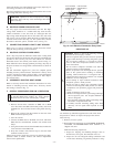
1. Inspect air filter(s) each month. Clean or replace when
necessary.
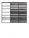
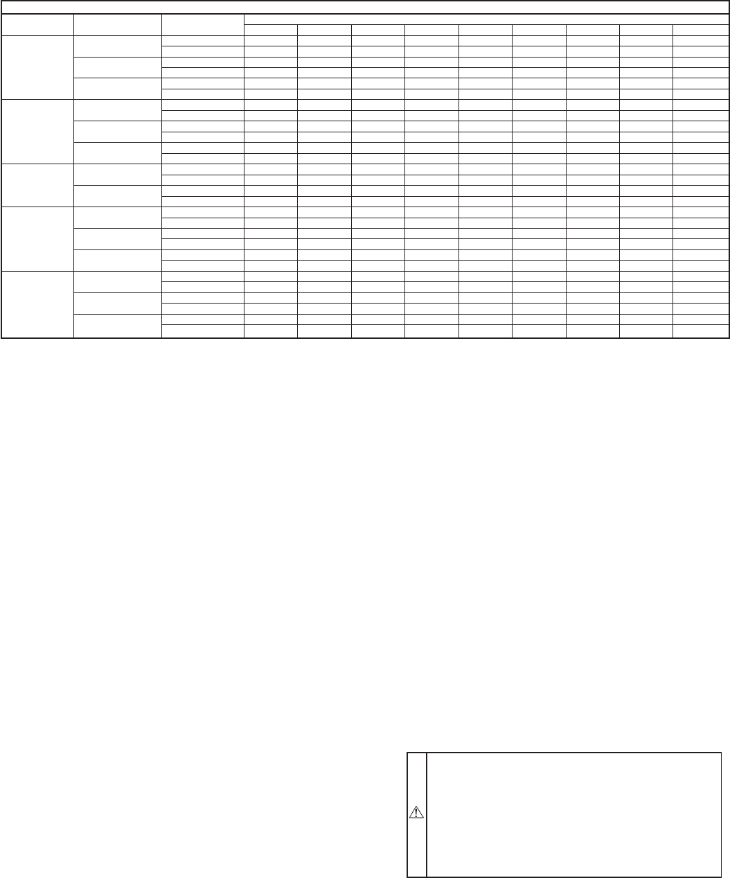
TABLE 4—DRY COIL AIR DELIVERY* HORIZONTAL DISCHARGE
(DEDUCT 10% FOR 208 VOLT OPERATION)
230 AND 460 VOLT
Unit Motor Speed Air Delivery
External Static Pressure (in. wg)
0.1 0.2 0.3 0.4 0.5 0.6 0.7 0.8 0.9
036
Low
Watts 450 435 420 400 380 335 326 311 -
Cfm 1231 1218 1204 1120 1008 950 863 751 -
Med
Watts 470 450 445 410 388 359 338 321 -
Cfm 1302 1264 1205 1163 1081 940 873 783 -
High
Watts 660 635 610 575 540 505 485 460 -
Cfm 1700 1660 1581 1450 1297 1190 1095 999 -
042
Low
Watts 478 458 440 411 378 350 327 317 -
Cfm 1303 1270 1224 1179 1126 1022 911 816 -
Med
Watts 481 468 450 438 404 370 338 320 735
Cfm 1310 1280 1241 1181 1110 1022 943 811 -
High
Watts - 798 678 647 618 578 540 500 -
Cfm - 1736 1688 1618 1510 1421 1309 1187 1060
048
Low
Watts - - 801 760 730 688 650 600 570
Cfm - - 1898 1841 1757 1682 1564 1429 1365
High
Watts - - 870 842 818 782 696 632 628
Cfm - - 2000 1903 1799 1718 1625 1446 1333
060†
2 Speed
Low
Watts 890 850 810 790 735 680 580 480 422
Cfm 1834 1820 1791 1762 1703 1640 1415 1159 950
Med
Watts 1040 1018 1000 950 890 835 790 650 580
Cfm 2230 2102 2025 1960 1901 1855 1752 1468 1121
High
Watts 1073 1038 1001 958 896 840 800 691 575
Cfm 2230 2202 2160 2122 2052 1926 1791 1588 1202
060
3 Speed
Low
Watts 1058 1008 942 891 860 828 750 700 630
Cfm 2384 2200 2197 2071 1989 1889 1820 1729 1640
Med
Watts 1266 1086 1021 1002 977 924 860 819 700
Cfm 2724 2476 2392 2344 2262 2132 2001 1910 1820
High
Watts 1301 1216 1197 1127 1058 1011 979 869 870
Cfm 2760 2618 2543 2423 2292 2169 2056 1943 1832
* Air delivery values are based on operating voltage of 230 v or 460 v, dry coil, without filter or electric heater. Deduct wet coil, filter and electric heater pressure drops to
obtain external static pressure available for ducting.
See Tables 5-7.
†460-v motors have 2 or 3 speeds (size 060 only).
NOTES:
1. Do not operate the unit at a cooling airflow that is less than 350 cfm for each 12,000 Btuh of rated cooling capacity. Evaporator coil frosting may occur at airflows below
this point.
2. Dashes indicate portions of the table that are beyond the blower motor capacity or are not recommended.
—15—