


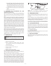

TABLE 3—ELECTRICAL DATA
UNIT 564A
SIZE
V-PH-HZ
VOLTAGE
RANGE
COMPRESSOR OFM IFM ELECTRIC HEAT POWER SUPPLY DISCONNECT SIZE
Min Max RLA LRA FLA FLA Nominal kW* FLA MCA MOCP FLA LRA
036 208/230-3-60 187 254 8.9 64.5 1.5 2.8
-/-
3.8/5.0
7.5/10.0
11.3/15
15.0/20.0
-/-
10.4/12.0
20.8/24.1
31.3/36.1
41.7/48.1
15.4/15.4
16.5/18.5
29.6/33.6
42.6/48.6
55.6/63.6
20/20
20/20
30/35
45/50
60/70†
15/15
15/17
27/31
39/45
51/59
74
042 208/230-3-60 187 254 10.9 73.0 1.5 2.8
-/-
3.8/5.0
7.5/10
11.3/15
15.0/20.0
-/-
10.4/12.0
20.8/24.1
31.3/36.1
41.7/48.1
17.9/17.9
17.9/18.5
29.6/33.6
42.6/48.6
55.6/63.6
25/25
25/25
30/35
45/50
60/70†
17/17
17/17
27/31
39/45
51/59
83
048 208/230-3-60 187 254 12.3 73.0 1.5 4.2
-/-
3.8/5.0
7.5/10
11.3/15
15.0/20.0
-/-
10.4/12.0
20.8/24.1
31.3/36.1
41.7/48.1
21.1/21.1
21.1/21.1
31.3/35.3
44.3/50.4
57.4/65.4
25/25
25/25
35/60
45/60
60/70†
21/21
21/21
29/32
41/46
53/60
87
060
208/230-3-60 187 254 16.3 114 1.4 5.8
-/-
3.8/5.0
7.5/10
11.3/15
15.0/20.0
-/-
10.4/12
23.8/24.1
31.3/36.1
47.7/48.1
27.5/27.5
27.5/27.5
33.3/37.3
46.3/52.3
59.3/67.3
35/35
35/35
35/40
50/60
60/70†
27/27
27/27
31/34
43/48
55/62
131
460-3-60 414 508 7.4 64.0 0.7 2.6
-
5
10
15
20
-
6
12
18
24
12.6
12.6
18.3
25.8
33.3
20
20
20
30
35
15
15
18
24
31
70
71
71
71
71
(See legend following Electrical Data charts)
452=5v
457=7v
455=2v
LEGEND
FLA — Full Load Amps
HACR — Heating, Air Conditioning and Refrigeration
IFM — Indoor-Fan Motor
LRA — Locked Rotor Amps
MCA — Minimum Circuit Amps
MOCP — Maximum Overcurrent Protection
(fuses or HACR-type circuit breaker)
NEC — National Electrical Code
OFM — Outdoor-Fan Motor
RLA — Rated Load Amps
UL — Underwriters Laboratories
* Single-Point Wiring Connections.
† Dual-Point Wiring Connections.
NOTES:
1.
2.
In compliance with NEC requirements for multimotor and
combination load equipment (refer to NEC Articles 430 and
440), the overcurrent protective device for the unit shall be
fuse or HACR breaker. The UL, Canada, units may be fuse
or circuit breaker.
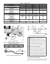
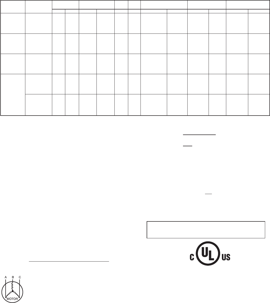
Unbalanced 3-Phase supply Voltage
Never operate a motor where a phase imbalance in supply
voltage is greater than 2%. Use the following formula to
determine the percent of voltage imbalance.
% Voltage imbalance
max voltage deviation from average voltage
= 100 x
average voltage
EXAMPLE: Supply voltage is 460-3-60.
AB = 452 v
BC = 464 v
AC = 455 v
452 + 464 + 455
Average Voltage =
3
1371
=
3
= 457
Determine maximum deviation from average voltage.
(AB) 457 -
(BC) 464 -
(AC) 457 -
Maximum deviation is 7 v.
Determine percent of voltage imbalance.
7
% Voltage Imbalance = 100 x
457
= 1.53%
This amount of phase imbalance is satisfactory as it is below the
maximum allowable 2%.
IMPORTANT: If the supply voltage phase imbalance is
more than 2%, contact your local electric utility company
immediately.
®
—14—