


—58—
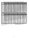
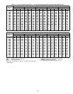
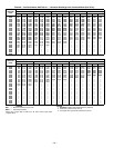
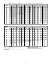
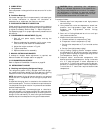
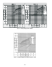
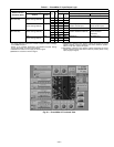
B. To Use Cooling Charging Charts
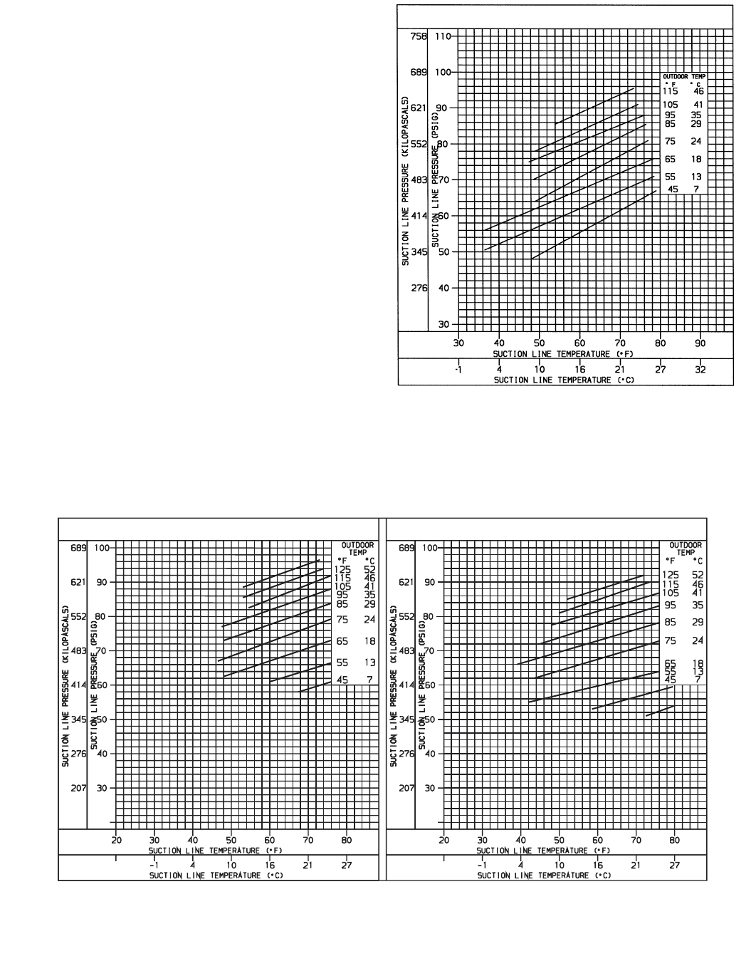
This method is to be used in Cooling mode only. Take the out-
door ambient temperature and read the suction pressure
gage. Refer to appropriate chart to determine what suction
temperature should be. If suction temperature is high, add
refrigerant. If suction temperature is low, carefully recover
some of the charge. Recheck the suction pressure as charge
is adjusted.
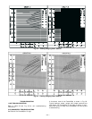
EXAMPLE: (Fig. 44; Circuit 1)
Outdoor Temperature . . . . . . . . . . . . . . . . . . . . . . . . . . . .85 F
Suction Pressure . . . . . . . . . . . . . . . . . . . . . . . . . . . . . .74 psig
Suction Temperature should be . . . . . . . . . . . . . . . . . . . .54 F
(Suction Temperature may vary ± 3 F.)
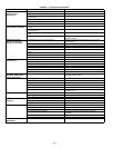
VIII. HIGH-PRESSURE SWITCH
Located on the compressor hot gas line is a high-pressure
switch. This switch opens at 428 psig and closes at 320 psig.
No adjustment is necessary. Refer to Tables 1A and 1B.
IX. LOSS-OF-CHARGE SWITCH
Located on the condenser liquid line is a low-pressure switch
which functions as a loss-of-charge switch. This switch con-
tains a Schrader core depressor. This switch opens at 7 psig
and closes at 22 psig. No adjustment is necessary. Refer to
Tables 1A and 1B.
X. FREEZESTAT
Located on the “hair pin” end of the evaporator coil is a
bimetal temperature sensing switch. This switch protects
the evaporator coil from freeze-up due to lack of airflow. The
switch opens at 30 F and closes at 45 F. No adjustment is
necessary. Refer to Tables 1A and 1B.
XI. REPLACEMENT PARTS
A complete list of replacement parts may be obtained from
any Bryant distributor upon request.
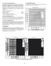
Fig. 41 — Cooling Charging Chart; 558F090
CIRCUITS 1 AND 2
CIRCUIT NO. 1
CIRCUIT NO. 2
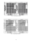
Fig. 42 — Cooling Charging Chart; 558F102