


—26—
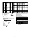
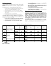
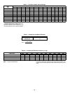
Table 3 — Supply Air Sensor
Temperature/Resistance Values
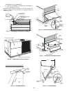
The temperature sensor looks like an eyelet terminal with
wires running to it. The sensor is located in the “crimp end”
and is sealed from moisture.
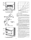
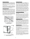
Outdoor Air Lockout Sensor
The EconoMi$er IV is equipped with an ambient tempera-
ture lockout switch located in the outdoor air stream which
is used to lockout the compressors below a 42 F ambient tem-
perature. See Fig. 17.
E. EconoMi$er IV Control Modes
Determine the EconoMi$er IV control mode before set up of the
control. Some modes of operation may require different sensors.
Refer to Table 4. The EconoMi$er IV is supplied from the
factory with a supply air temperature sensor and an outdoor
air temperature sensor. This allows for operation of the
EconoMi$er IV with outdoor air dry bulb changeover control.
Additional accessories can be added to allow for different
types of changeover control and operation of the EconoMi$er
IV and unit.
Outdoor Dry Bulb Changeover
The standard controller is shipped from the factory config-
ured for outdoor dry bulb changeover control. The outdoor
air and supply air temperature sensors are included as
standard. For this control mode, the outdoor temperature is
compared to an adjustable set point selected on the control.
If the outdoor-air temperature is above the set point, the
EconoMi$er IV will adjust the outdoor-air dampers to
minimum position. If the outdoor-air temperature is below
the set point, the position of the outdoor-air dampers will be
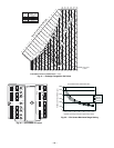
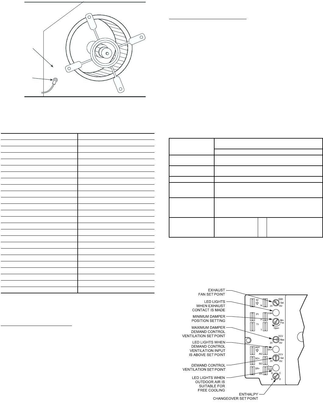
controlled to provide free cooling using outdoor air. When in
this mode, the LED next to the free cooling set point potenti-
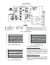
ometer will be on. The changeover temperature set point is
controlled by the free cooling set point potentiometer located
on the control. See Fig. 28. The scale on the potentiometer is
A, B, C, and D. See Fig. 29 for the corresponding temperature
changeover values.
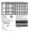
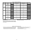
Table 4 — EconoMi$er IV Sensor Usage
*CRENTDIF004A00 and CRTEMPSN002A00 accessories are used on
many different base units. As such, these kits may contain parts that will
not be needed for installation.
†33ZCSENCO2 is an accessory CO
2
sensor.
**33ZCASPCO2 is an accessory aspirator box required for duct-mounted
applications.
††CRCBDIOX005A00 is an accessory that contains both 33ZCSENCO2
and 33ZCASPCO2 accessories.
TEMPERATURE (F) RESISTANCE (ohms)
–58 200,250
–40 100,680
–22 53,010
–4 29,091
14 16,590
32 9,795
50 5,970
68 3,747
77 3,000
86 2,416
104 1,597
122 1,080
140 746
158 525
176 376
185 321
194 274
212 203
230 153
248 116
257 102
266 89
284 70
302 55
APPLICATION
ECONOMI$ER IV WITH OUTDOOR AIR
DRY BULB SENSOR
Accessories Required
Outdoor Air
Dry Bulb
None. The outdoor air dry bulb sensor
is factory installed.
Differential
Dry Bulb
CRTEMPSN002A00*
Single Enthalpy HH57AC078
Differential
Enthalpy
HH57AC078
and
CRENTDIF004A00*
CO
2
for DCV
Control using a
Wall-Mounted
CO
2
Sensor
33ZCSENCO2
CO
2
for DCV
Control using a
Duct-Mounted
CO
2
Sensor
33ZCSENCO2†
and
33ZCASPCO2**
OR
CRCBDIOX005A00††
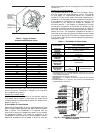
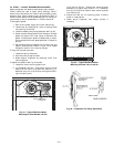
SUPPLY AIR
TEMPERATURE
SENSOR
MOUNTING
LOCATION
SUPPLY AIR
TEMPERATURE
SENSOR
Fig. 27 — Supply Air Sensor Location
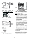
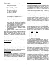
Fig. 28 — EconoMi$er IV Controller Potentiometer
and LED Locations