


—57—
II. LUBRICATION
A. Compressors
Each compressor is charged with correct amount of oil at the
factory.
B. Fan-Motor Bearings
Fan-motor bearings are of the permanently lubricated type.
No further lubrication is required. No lubrication of
condenser-fan or evaporator-fan motors is required.
III. EVAPORATOR FAN BELT INSPECTION
Check condition of evaporator belt or tension during heating
and cooling inspections or as conditions require. Replace belt
or adjust as necessary. Refer to Step 7 — Adjust Evaporator-
Fan Speed on page 31 for proper adjustment procedures and
belt tension.
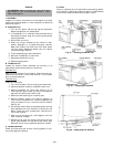
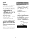
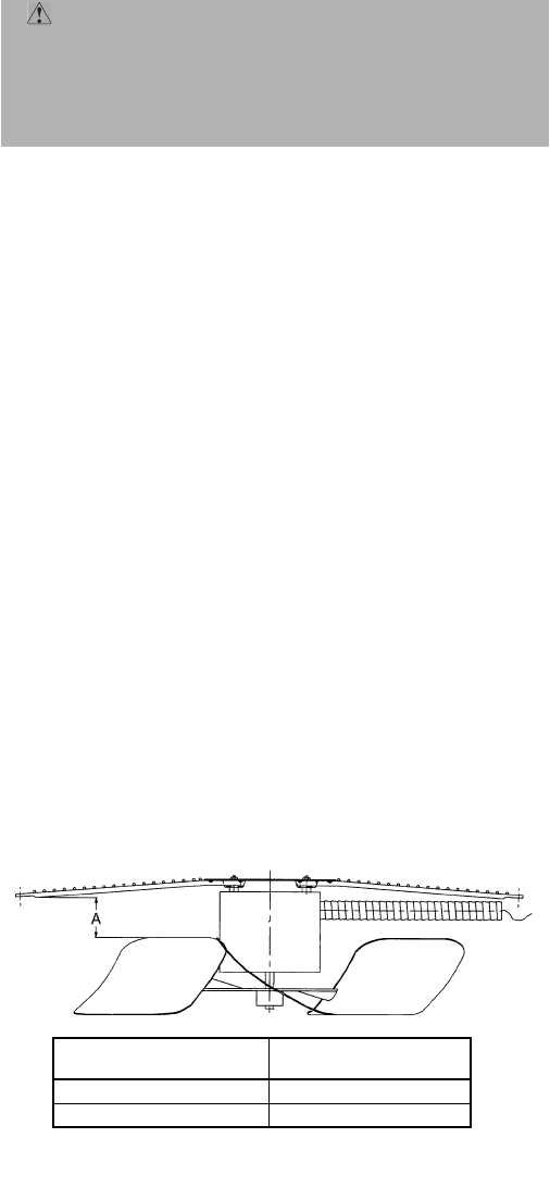
IV. CONDENSER-FAN ADJUSTMENT (Fig. 40)
1. Shut off unit power supply, lockout and tag the
disconnect.
2. Remove condenser-fan assembly (grille, motor, motor
cover, and fan) and loosen fan hub setscrews.
3. Adjust fan height as shown in Fig. 40.
4. Tighten setscrews.
5. Replace condenser-fan assembly.
V. MANUAL OUTDOOR-AIR DAMPER
If outdoor-air damper blade adjustment is required, see
Manual Outdoor-Air Damper section on page 22.
VI. ECONOMIZER ADJUSTMENT
Refer to Optional EconoMi$er IV section on page 23.
VII. REFRIGERANT CHARGE
A. Checking and Adjusting Refrigerant Charge
The refrigerant system is fully charged with R-22 refriger-
ant, tested, and factory-sealed. Unit must operate in Cooling
mode a minimum of 10 minutes before checking charge.
NOTE: Adjustment of the refrigerant charge is not required
unless the unit is suspected of not having the proper R-22
charge.
A superheat charging chart is attached to the outside of the
service access panel. The chart includes the required suction
line temperature at given suction line pressures and outdoor
ambient temperatures.
An accurate superheat, thermocouple-type or thermistor-
type thermometer, and a gage manifold are required when
using the superheat charging method for evaluating the unit
charge. Do not use mercury or small dial-type thermometers
because they are not adequate for this type of measurement.
Proceed as follows:
1. Remove caps from low-pressure and high-pressure
service fittings.
2. Using hoses with valve core depressors, attach low-
pressure and high-pressure gage hoses to low-
pressure and high-pressure service fittings,
respectively.
3. Start unit in Cooling Mode and let unit run until sys-
tem pressures stabilize.
4. Measure and record the following:
a. Outdoor ambient-air temperature (F db).
b. Evaporator inlet-air temperature (F wb).
c. Suction-tube temperature (F) at low-side service
fitting.
d. Suction (low-side) pressure (psig).
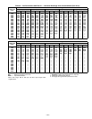
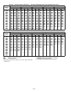
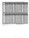
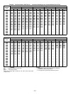
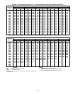
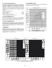
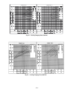
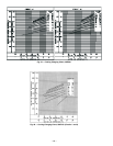
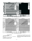
5. Using “Cooling Charging Charts” compare outdoor-
air temperature (F db) with the suction line pressure
(psig) to determine desired system operating suction
line temperature. See Fig. 41-48.
6. Compare actual suction-tube temperature with
desired suction-tube temperature. Using a tolerance
of ± 3° F, add refrigerant if actual temperature is
more than 3° F higher than proper suction-tube tem-
perature, or remove refrigerant if actual temperature
is more than 3° F lower than required suction-tube
temperature.
CAUTION: When evaluating the refrigerant
charge, an indicated adjustment to the specified fac-
tory charge must always be very minimal. If a substan-
tial adjustment is indicated, an abnormal condition
exists somewhere in the cooling system, such as insuf-
ficient airflow across either coil or both coils.
Fig. 40 — Condenser Fan Adjustment
558F
FAN HEIGHT
‘‘A’’, in.
208/230 V 2.75
460 and 575 V 3.50