


—27—
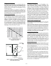
Differential Dry Bulb Control
For differential dry bulb control the standard outdoor dry
bulb sensor is used in conjunction with an additional acces-
sory dry bulb sensor (part number CRTEMPSN002A00). The
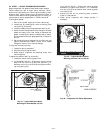
accessory sensor must be mounted in the return airstream.
See Fig. 30. Wiring is provided in the EconoMi$er IV wiring
harness. See Fig. 23.
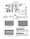
In this mode of operation, the outdoor-air temperature is
compared to the return-air temperature and the lower tem-
perature airstream is used for cooling. When using this mode
of changeover control, turn the enthalpy set point potentiom-
eter fully clockwise to the D setting. See Fig. 28.
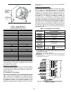
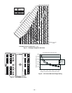
Outdoor Enthalpy Changeover
For enthalpy control, accessory enthalpy sensor (part num-
ber HH57AC078) is required. Replace the standard outdoor
dry bulb temperature sensor with the accessory enthalpy
sensor in the same mounting location. See Fig. 17. When the
outdoor air enthalpy rises above the outdoor enthalpy
changeover set point, the outdoor-air damper moves to its
minimum position. The outdoor enthalpy changeover set
point is set with the outdoor enthalpy set point potentiome-
ter on the EconoMi$er IV controller. The set points are A, B,
C, and D. See Fig. 31. The factory-installed 620-ohm jumper
must be in place across terminals SR and SR+ on the
EconoMi$er IV controller. See Fig. 17 and 32.
Differential Enthalpy Control
For differential enthalpy control, the EconoMi$er IV con-
troller uses two enthalpy sensors (HH57AC078 and
CRENTDIF004A00), one in the outside air and one in the
return air duct. The EconoMi$er IV controller compares the
outdoor air enthalpy to the return air enthalpy to determine
EconoMi$er IV use. The controller selects the lower enthalpy
air (return or outdoor) for cooling. For example, when the out-
door air has a lower enthalpy than the return air, the
EconoMi$er IV opens to bring in outdoor air for free cooling.
Replace the standard outside air dry bulb temperature sensor
with the accessory enthalpy sensor in the same mounting loca-
tion. See Fig. 17. Mount the return air enthalpy sensor in the
return air duct. See Fig. 30. Wiring is provided in the
EconoMi$er IV wiring harness. See Fig. 23. The outdoor
enthalpy changeover set point is set with the outdoor enthalpy
set point potentiometer on the EconoMi$er IV controller. When
using this mode of changeover control, turn the enthalpy set
point potentiometer fully clockwise to the D setting.
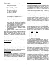
Indoor Air Quality (IAQ) Sensor Input
The IAQ input can be used for demand control ventilation
control based on the level of CO
2
measured in the space or
return air duct.
Mount the accessory IAQ sensor according to manufacturer
specifications. The IAQ sensor should be wired to the AQ and
AQ1 terminals of the controller. Adjust the DCV potentiome-
ters to correspond to the DCV voltage output of the indoor air
quality sensor at the user-determined set point. See Fig. 33.
If a separate field-supplied transformer is used to power the
IAQ sensor, the sensor must not be grounded or the
EconoMi$er IV control board will be damaged.
Exhaust Set Point Adjustment
The exhaust set point will determine when the exhaust fan
runs based on damper position (if accessory power exhaust is
installed). The set point is modified with the Exhaust Fan
Set Point (EXH SET) potentiometer. See Fig. 28. The set
point represents the damper position above which the
exhaust fans will be turned on. When there is a call for
exhaust, the EconoMi$er IV controller provides a 45 ± 15
second delay before exhaust fan activation to allow the
dampers to open. This delay allows the damper to reach the
appropriate position to avoid unnecessary fan overload.
Minimum Position Control
There is a minimum damper position potentiometer on the
EconoMi$er IV controller. See Fig. 28. The minimum damper
position maintains the minimum airflow into the building
during the occupied period.
When using demand ventilation, the minimum damper posi-
tion represents the minimum ventilation position for VOC
(volatile organic compound) ventilation requirements. The
maximum demand ventilation position is used for fully occu-
pied ventilation.
When demand ventilation control is not being used, the min-
imum position potentiometer should be used to set the occu-
pied ventilation position. The maximum demand ventilation
position should be turned fully clockwise.
Adjust the minimum position potentiometer to allow the
minimum amount of outdoor air, as required by local codes,
to enter the building. Make minimum position adjustments
with at least 10 F temperature difference between the out-
door and return-air temperatures.
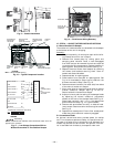
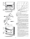
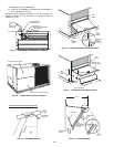
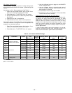
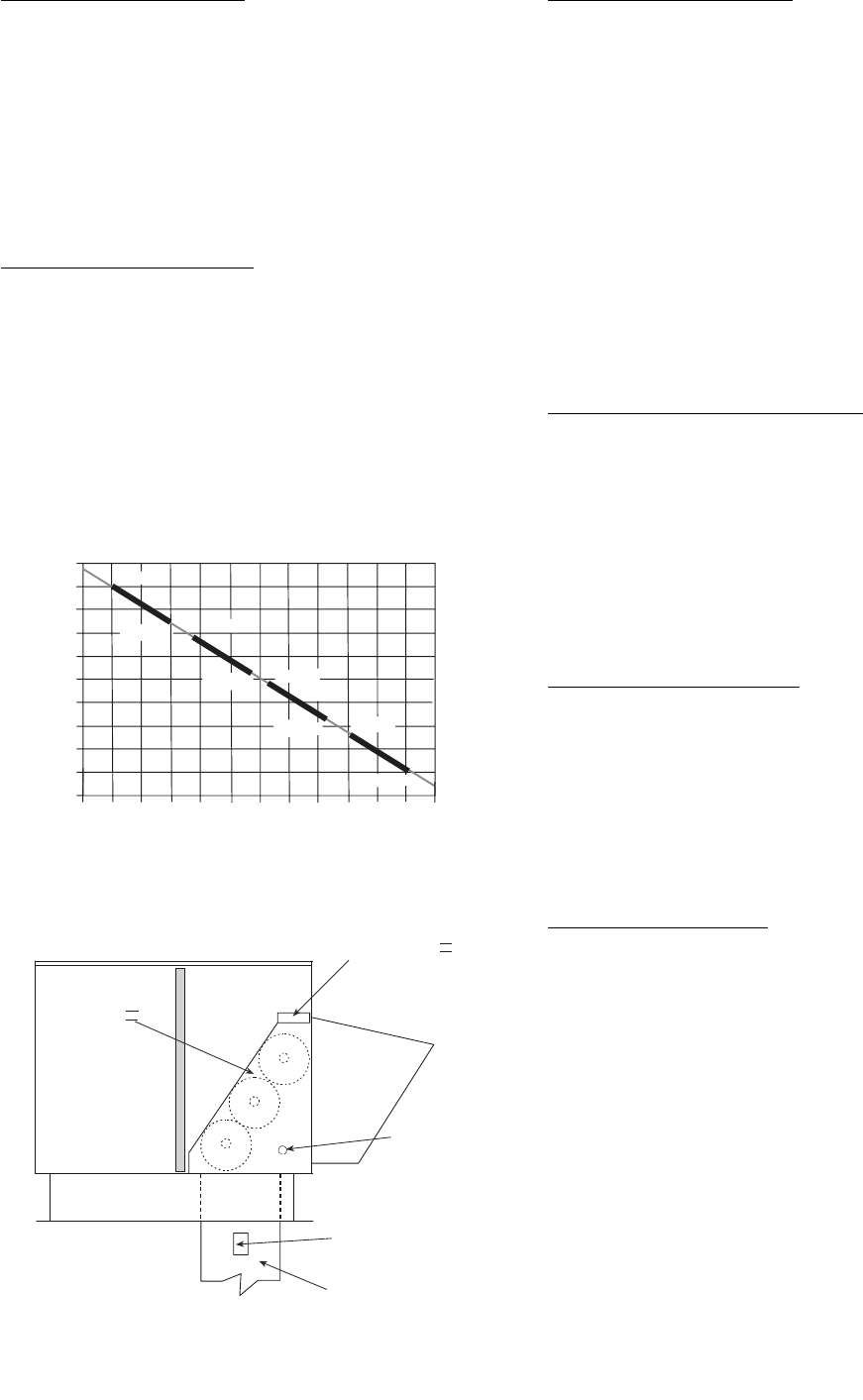
Fig. 30 — Return Air Temperature or Enthalpy
Sensor Mounting Location
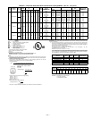
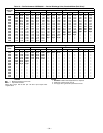
LED ON
LED ON
LED ON
LED ON
LED OFF
19
18
LED OFF
LED OFF
LED OFF
17
16
15
14
13
12
11
10
9
40
45
50
55
60
65
70
75
80
85
90
95
100
DEGREES FAHRENHEIT
mA
D
C
B
A
Fig. 29 — Outside Air Temperature
Changeover Set Points
ECONOMI$ER IV
ECONOMI$ER IV
CONTROLLER
GROMMET
RETURN AIR
SENSOR
RETURN DUCT
(FIELD-PROVIDED)