


—22—
VI. STEP 6 — ADJUST FACTORY-INSTALLED OPTIONS
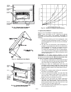
A. Manual Outdoor-Air Damper
The outdoor-air hood and screen are attached to the basepan
at the bottom of the unit for shipping.
Assembly:
1. Determine quantity of ventilation required for build-
ing. Record amount for use in Step 8.
2. Remove filter access panel by raising panel and
swinging panel outward. Panel is now disengaged
from track and can be removed. No tools are required
to remove the filter access panel. Remove outdoor-air
opening panel. Save panels and screws. See Fig. 13.
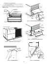
3. Separate hood and screen from basepan by removing
the screws and brackets securing them. Save all
screws and discard brackets.
4. Replace outdoor air opening panel.
5. Place hood on front of outdoor air opening panel. See
Fig. 14 for hood details. Secure top of hood with the
6 screws removed in Step 3. See Fig. 15.
6. Remove and save 8 screws (4 on each side) from sides
of the manual outdoor-air damper.
7. Align screw holes on hood with screw holes on side of
manual outdoor-air damper. See Fig. 14 and 15.
Secure hood with 8 screws from Step 6.
8. Adjust minimum position setting of the damper blade
by adjusting the manual outdoor-air adjustment
screws on the front of the damper blade. See Fig. 13.
Slide blade vertically until it is in the appropriate
position determined by Fig. 16. Tighten screws.
9. Remove and save screws currently on sides of hood.
Insert screen. Secure screen to hood using the screws.
See Fig. 15.
10. Replace filter access panel. Ensure filter access panel
slides along the tracks and is securely engaged.
B. Convenience Outlet
An optional convenience outlet provides power for rooftop
use. For maintenance personnel safety, the convenience out-
let power is off when the unit disconnect is off. Adjacent unit
outlets may be used for service tools. An optional “Hot Out-
let” is available from the factory as a special order item.
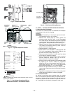
MAIN
CONTROL
BOX
BOX
SINGLE
POINT BOX
MOUNTING SCREW
DISCONNECT
MOUNTING
LOCATION
EMT OR RIGID
CONDUIT
(FIELD SUPPLIED)
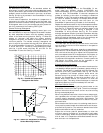
BRACKET AND
CONDUIT DRIP
BOOT
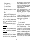
CENTER
POST
COM-
PRESSOR
NO. 1
SINGLE
POINT
COM-
PRESSOR
NO. 2
Fig. 9 — Conduit Installation
LEGEND
EMT — Electro-Metallic Tubing
Fig. 10 — Typical Component Location
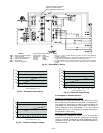
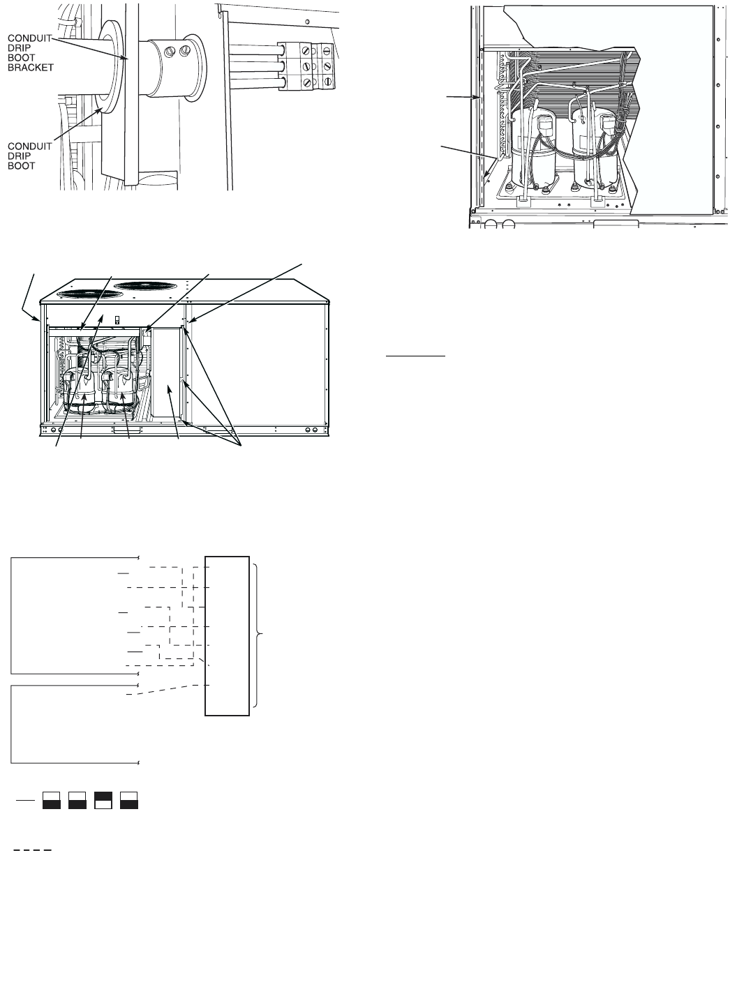
WIRE
CONNECTIONS
TO
LOW-VOLTAGE
SECTION
COOL STAGE 1
FAN
HEAT STAGE 1
COOL STAGE 2
HEAT STAGE 2
24 VAC HOT
24 VAC COM
N/A
OUTDOOR AIR
SENSOR
Y1/W2
G
W/W1
Y/Y2
O/W2
R
C
S1
S2
THERMOSTAT DIPSWITCH SETTINGS
R
G
Y1
Y2
W1
W2
C
IPD/X
ON
OFF
A
B
C
D
LEGEND
NOTE: Underlined letter indicates active thermostat output when con-
figured for A/C operation.
Fig. 11 — Low-Voltage Connections With or
Without Economizer or Two-Position Damper
Field Wiring
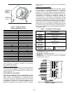
RACEWAY
HOLE IN
END PANEL
(HIDDEN)
Fig. 12 — Field Control Wiring Raceway