16
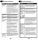
SYMPTOM
POTENTIAL SOLUTION
Thermostat will not
allowme to program
a setpoint
temperature lower
than45˚ F (7˚ C).
Thisisbelowthe normalthermostattemperaturesetting range
of45˚ to 90˚F (7˚ to 32˚ C).
Fan continues to run
all the time whether
the system is on or
off.
Check that thefan controlswitchisin theAUTOposition. This
willallowthefan to runonly when the heating or coolingsystem
isturnedonand running.
Check thermostat wiringto makesurethatthe fan control
wiringis connectedto the correct terminals on the wiring
terminalblock. SeeInstallation and Wiring Diagramssectionsof
thismanual.
Fan continues to run
in cooling mode when
the system has
turned off.
TheResidualCoolingFan ControlFeaturecan allow up to a90
secondfan delay aftercoolingsystem shutdownforenergy
efficiency gains. The defaultsettingis60 seconds. This can be
changedto disablethisfeatureorshortenthetimeperiodif
desired. SeeSetting ResidualCoolingFanFeaturesectionof
thismanual.
The room is too
warmor too cold.
SeeReviewSetTemperaturesectionofthismanualto verifythe
currentsetpoint and make anymodificationsthatarenecessary.
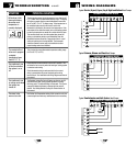
LO is shown in the
thermostat display
where the room
temperature is
normallydisplayed.
Thetemperaturesensed by the thermostat is lowerthanthe 40˚
F(5˚ C)lower limitof thethermostatsdisplay range. The display
willreturn to normalafter the sensedtemperature riseswithin
the40˚to 99˚F (5˚ to 37˚C) display range. If the temperaturein
thecontrolledspaceseems to benormal,wait for the
thermostattoacclimateto the correct room temperature. If the
roomseemstobe colderthanusual,turnon theheatingsystem
toraisethetemperatureas needed for comfort withintheroom.
Thisconditioncouldoccur from the systembeing turnedoff
duringa coldweatherperiodoruponinstallationwhenthe
thermostathasbeenstoredfora longperiodoftimein acold
vehicleorlocationprior to beinginstalled. Thethermostat
shouldbe allowedtowarmup priortoinstallationto allow
properheatingcontrol once installed.
TROUBLESHOOTING
7
cont.
17
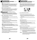
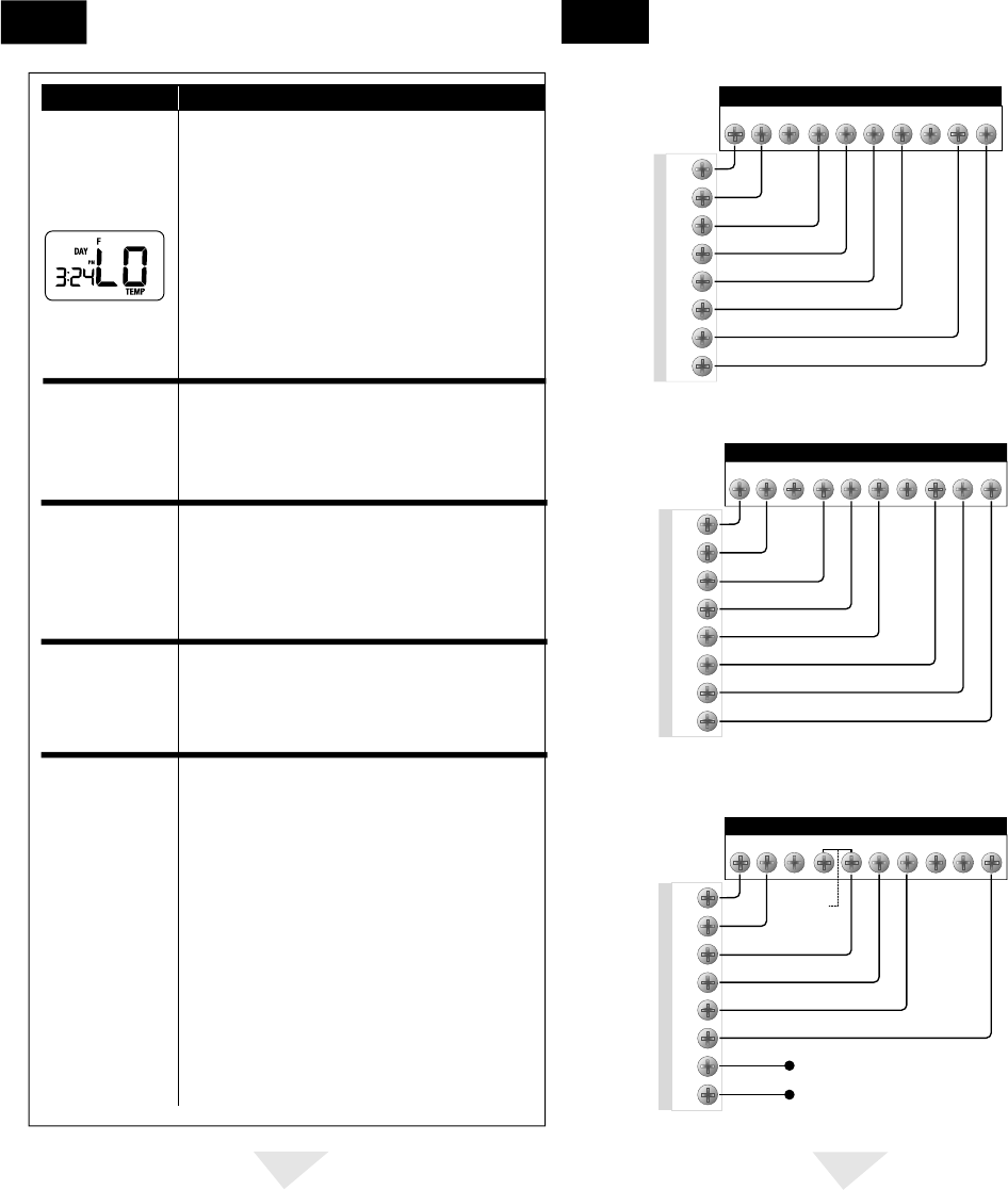
Typical Carrier, Bryant, Payne, Day & Night and Reliant Heat Pumps
WIRING DIAGRAMS
8
THERMOSTAT TERMINAL BLOCK
HEATPUMPPCB
R
R
Y
W2
E
G
O
LorX
C
Y1 Y2 W2 E G
O
B L C
Typical Comfortmaker and Heil-Quaker Heat Pumps
THERMOSTAT TERMINAL BLOCK
HEATPUMPPCB
R
CAPPED
CAPPED
R
Y
W1
G
O
C
W2
X
Y1 Y2
W2 E
G O B L C
Typical Coleman, Rheem and Ruud Heat Pumps
THERMOSTAT TERMINAL BLOCK
HEATPUMPPCB
R
R
Y
W2
E
G
B
L
X
Y1 Y2 W2 E G O
B
L C
User
Supplied
Jumper


