12
NOTE: The installer can resetthe thermostat andbypass the compressor protection
features bypressing the RESET button. This willerase all entered programs,current
time ofday,day of week andother user settings andshould only be usedduring
installation fortesting purposes or toreset a thermostat to regain normaloperation.
This willreturn allThermostat settingsto their defaultvalues. The user willhave to
re-program allof the erased settings.
NOTE: Resetting the thermostat bypressing the RESETbutton will erase allentered
programs,current time of day, day ofweek and other usersettings.
This willreturn allThermostat settingsto their defaultvalues. Changing ˚F /˚C temperature
scale defaultshould be done priorto installation and beforeanyprogramming toavoid loss
during resetstep.
NOTE: This thermostat requires24 VoltAC power fornormal operation andcontrol of
the heatingor cooling systems. This thermostat alsorequires two (2) properlyinstalled
"AA" alkalinebatteries to retain usersettings and programs inthe event of lossof AC
Power due topo wer outage orrolling blackouts.
6.5
Compressor Protection cont.
6.7
Changing Fahrenheit (°F) to Celsius (°C)
6.6
High Temperature Safety Switch
While the thermostatis in the HEATmode of operation(selectorswitchin theHEAT position),
thethermostatwillmechanically turn-offifthe room temperatureraiseshigherthan99˚F
(37˚C). Thereis also asoftwarefeature that willautomaticallyturn-offthethermostatin
HEATmode if the temperatureraiseshigher than 93˚ F(34˚C).
WARNING!
Read BEFORE proceeding
Press RESETbutton using apaper clip ora small pencil tip. This willreset the
thermostat andreturn all settings totheir default values. Verify yourthermostatis
controlling yoursystem, see TestingYour NewThermostat. If theproblems still persist,
call aprofessional service technicianimmediately to verifyproper system operation.
6.8
Low Battery Detection and Replacement
1.
Releasethe frontthermostatbody from the rearthermostatbody by pressingthe release
latchonthe bottomof thethermostat.
2.
Gentlyseparatethetwothermostat halvesandturn the frontthermostatbodyoverexposing
therearviewof the circuit board.
3.
Locate the internal˚F /˚Cswitchon the circuitboard.
4.
Using your fingers,gentlyfliptheswitchtowardsthepreferredtemperature˚F/ ˚Cscale.
5.Reattach
thefrontthermostatbodyby locatingthe top mountinglugsand swingingthe
thermostatdownuntilthereleaselatchlocks.
6.
Press the RESETbutton on the frontof thethermostatusinga paperclipora smallpencil
tip. This will registerthenewtemperaturescaledefault.
Thisthermostatisequipped with alowbatterydetectionfeaturethatconstantlymonitorsthe
back-upbatteriesduringnormaloperatingmodeto determine whethertheyhavesufficient
powertoprovideproper back-upoperation.
ADDITIONAL
OPERATION FEATURES
6
cont..
13
6.9
Resetting Thermostat
6.8
Low Battery Detection and Replacement cont.
Whenthisfeature determinesthat the back-up batteriesstatus is low,lowbatteryindicator
willappear in the display. Thethermostatwillcontinueto functionnormally ifAC poweris
provided,butit is stronglyrecommendedto changetheback-up batteries as soonas
possibleto avoid possibleprogramlossdue toAC poweroutageorrollingblackouts. This
thermostatrequires24VoltACPowerfornormaloperationand controlofthe heatingor
coolingsystems.
Replacing the Back-up Batteries
6.8.1
1.
Openfrontthermostatdoorandlocatethebatterycompartmentdoor.
2.
Gentlyremovethetwo "AA" alkalinebatterieslocatedinthe battery compartment.
3.
Installtwo new "AA"alkalinebatteries into battery compartment. Makesureto match
thepositive(+) ends of the batterieswiththepositive(+) terminalslocatedin the
battery compartment.
4.
Close battery compartmentand verifythatthe low batteryindicator does not appearin
thedisplay.
TheResetfeature allowsthe user tocompletelyresetthethermostat to registernew manual
˚F/ ˚C temperaturescaleswitchsettings.
1.
To eraseall enteredprograms,currenttimeofday,day of weekand other user settings,
gentlypressRESETbuttonusingapaper clipor asmallpenciltip.
2.
Thiswillreturn allThermostatsettingsto theirdefaultvaluesandregister all newmanual
˚F/ ˚C temperaturescaleswitchsettings.
6.10
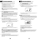
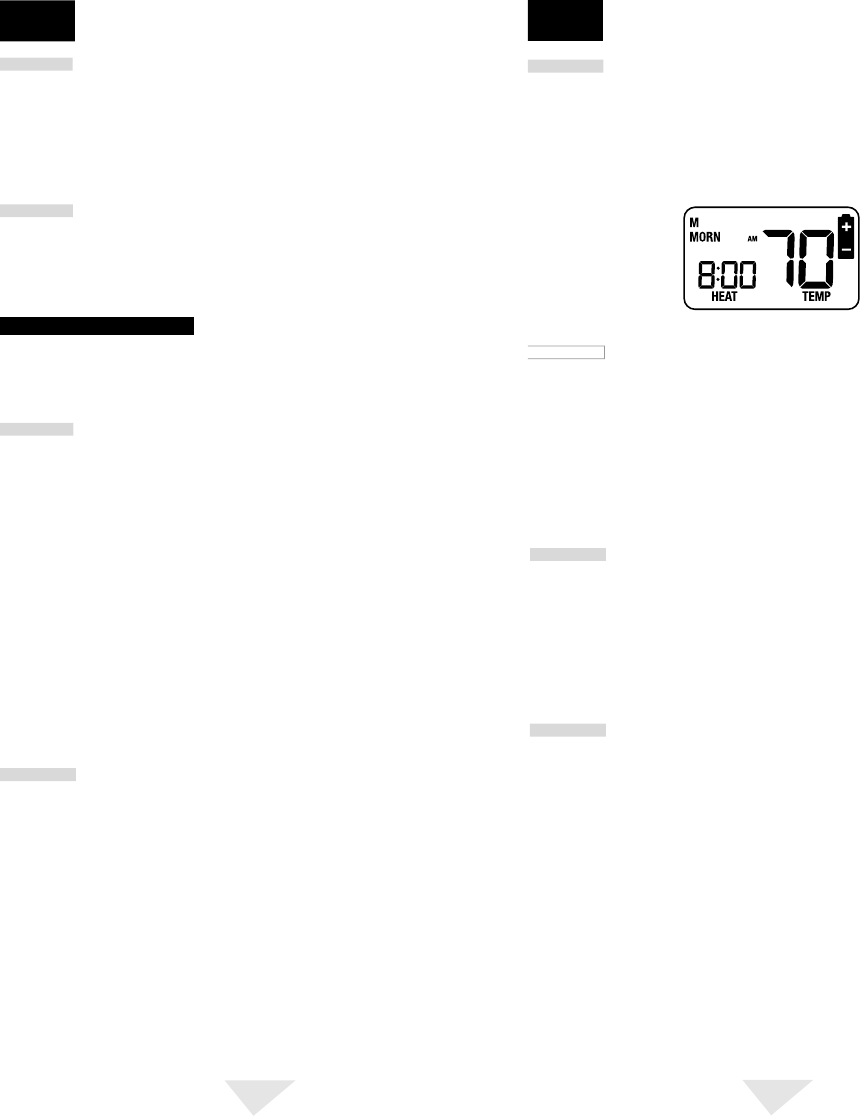
Multi-Colored LED Status Indicators
Thethreemulti- coloredLEDStatusIndicatorslocatedonthe front of yourthermostatabovethe
displaywillnotifyyouof keysysteminformation.
AUX(Green): This will turn on whenthe auxiliarysecond stage of heatingisactive. The
auxiliarystageof heating is usually the leasteconomicalstageofheat.
CHECK (Red):Indicatorwillactivate when amalfunctionoccursinthe heat pumpsystem.
Whenthelightis active,calla professional servicetechnicianto verifysystem
performanceand switchthesystem to EmergencyHeatModeif requiredto
maintainroomtemperature.
EMER(Red): Thisindicatorwilllightwhenyou selectEmergencyHeatModeof operationusing
thesystemselectorswitch. WhenyouselectEmergency Heat Mode,theheat
pumpstageofheat is turnedoffand the emergency (auxiliary) stage of heatingis
usedtomaintain the setpointtemperature.
ADDITIONAL
OPERATION FEATURES
6
cont.


