


3. Adjust temperature rise by adjusting blower speed. Increase
blower speed to reduce temperature rise. Decrease blower
speed to increase temperature rise.
WARNING: Disconnect 115-v electrical power before
changing speed tap. Failure to follow this warning could
result in personal injury.
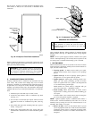
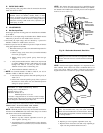
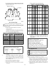
4. To change blower motor speed selections for heating mode,
remove blower motor lead from control center HEAT
terminal. (See Fig. 25.) Select desired blower motor speed
lead from 1 of the other terminals and relocate it to HEAT
terminal. See Table 12 for lead color identification. Recon-
nect original lead on SPARE terminal.
Follow this same procedure for proper selection of COOL
speed selection.
C. Blower Off Delay (Heat Mode)
The main blower off time delay period is factory-set at 135 sec and
is not field-adjustable.
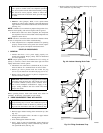
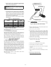
D. Set Thermostat Heat Anticipator
Thermostat heat anticipator must be set to match amp draw of
components in R-W circuit. Accurate amp draw measurements can
be obtained at thermostat subbase terminals R and W.
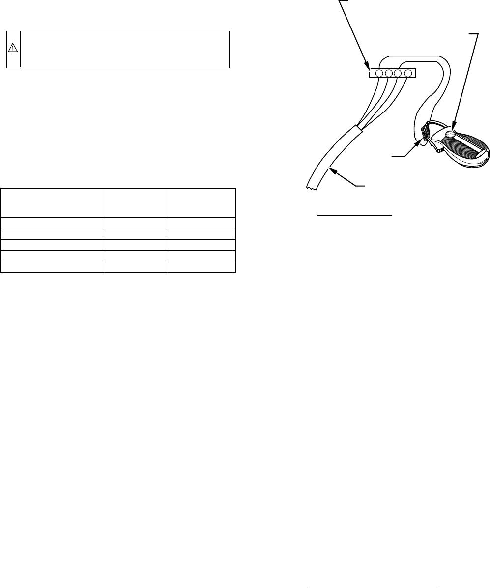
Fig. 46 illustrates an easy method of obtaining these measure-
ments. Amp reading should be taken after blower motor has
started. See thermostat manufacturer’s instructions for adjusting
heat anticipator and for varying heating cycle length.
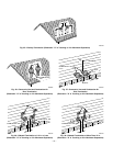
CHECK SAFETY CONTROLS
I. CHECK PRIMARY LIMIT CONTROL
This control shuts off combustion control system and energizes
air-circulating blower motor if furnace overheats. Recommended
method of checking this limit control is to gradually block off
return air after furnace has been operating for a period of at least
5 minutes. As soon as limit control has shut off burners, return-air
opening should be unblocked to permit normal air circulation. By
using this method to check limit control, it can be established that
limit is functioning properly and operates if there is a restricted
return-air supply or motor failure. If limit control does not function
during this test, cause must be determined and corrected.
II. CHECK PRESSURE SWITCH
This control proves operation of draft inducer. Check switch
operation as follows:
1. Turn off 115-v power to furnace.
2. Remove main furnace door and disconnect inducer motor
lead wires from wire harness.
3. Turn on 115-v power to furnace.
4. Set thermostat to call for heat and wait 1 minute. When
pressure switch is functioning properly, hot surface ignitor
should NOT glow, and control center diagnostic light
flashes a Status Code 31. If hot surface ignitor glows when
inducer motor is disconnected, shut furnace down immedi-
ately. Determine reason pressure switch did not function
properly and correct condition.
5. Turn off 115-v power to furnace.
6. Reconnect inducer motor leads, reinstall main furnace door,
and turn on 115-v power supply.
CHECKLIST
1. Put away tools and instruments. Clean up debris.
2. Verify manual reset switch has continuity.
3. Verify that blower and control access doors are properly
installed.
4. Cycle test furnace with room thermostat.
5. Check operation of accessories per manufacturer’s instruc-
tions.
6. Review User’s Guide with owner.
7. Leave literature packet near furnace.
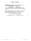
TABLE 12—SPEED SELECTOR
COLOR SPEED
FACTORY-
SHIPPED
CONNECTION
Black High Cool
Yellow (When Present) Medium High Spare
Blue Medium Low Heat
Red Low Spare
White Common Com
Fig. 46—Amp Draw Check with Ammeter
A80201
R Y W G
10 TURNS
THERMOSTAT SUBBASE
TERMINALS WITH
THERMOSTAT REMOVED
HOOK-AROUND
VOLT/AMMETER
EXAMPLE:
5.0 AMPS ON AMMETER
10 TURNS AROUND JAWS
= 0.5 AMPS FOR THERMOSTAT SETTING
FROM UNIT 24-VOLT
TERMINAL BLOCK
—41—