


CAUTION: When combustion-air pipe is installed
above a suspended ceiling, pipe must be insulated with
3/8-in. thick Armaflex-type insulation. Combustion-air
pipe should also be insulated when it passes through
warm, humid space.
CAUTION: When vent pipe is exposed to temperatures
below freezing, such as when it passes through an
unheated space or when a chimney is used as a raceway,
pipe must be insulated as shown in Table 7 with
Armaflex-type insulation.
CAUTION: Combustion air must not be taken from
inside structure because inside air is frequently contami-
nated by halogens, which include fluorides, chlorides,
bromides, and iodides. These elements are found in
aerosols, detergents, bleaches, cleaning solvents, salts, air
fresheners, adhesives, paint, and other household prod-
ucts. Locate combustion-air inlet as far as possible from
swimming pool and swimming pool pump house.
Excessive exposure to contaminated combustion air will
result in safety and performance related problems.
WARNING: Solvent cements are combustible. Keep
away from heat, sparks, and open flame. Use only in
well-ventilated areas. Avoid breathing in vapor or allow-
ing contact with skin or eyes. Failure to follow this
warning could result in fire, property damage, personal
injury, or death.
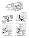
WARNING: All combustion-air and vent pipes must be
airtight and watertight. Pipes must also terminate exactly
as shown in Fig. 30, 31, 32, 33, or 34. Failure to follow
this warning could result in property damage, personal
injury, or death.
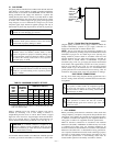
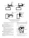
NOTE: The minimum combustion-air and vent pipe length (each)
for these furnaces is 5 ft. Short pipe lengths (5-8 ft) may discharge
water droplets. These droplets may be undesirable, and a 12-in.
minimum offset pipe section is recommended, as shown in Fig. 28,
to reduce excessive droplets from exiting vent pipe outlet.
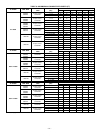
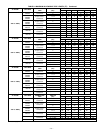
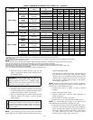
B. Combustion-Air and Vent Pipe Diameter
Determine combustion-air and vent pipe diameter.
1. Using Table 6, individually determine the combustion-air
and vent pipe diameters. Pick the larger of these 2 pipe
diameters and use this diameter for both combustion-air and
vent pipes.
2. When installing vent systems of short pipe length, use the
smallest allowable pipe diameter. Do not use pipe size
greater than required or incomplete combustion, flame
disturbance, or flame sense lockout may occur.
NOTE: Do not count elbows or pipe sections in terminations or
within furnace. See shaded areas in Fig. 30, 31, 32, 33, and 34.
EXAMPLE:
An 036080 size furnace located in Indianapolis, elevation
650 ft above sea level, could be installed in an application
requiring 3 elbows and 32 ft of vent pipe, along with 5
elbows and 34 ft of combustion-air pipe. Table 6 indicates
this application would allow a 2-in. diameter vent pipe, but
require a 2-1/2 in. diameter combustion air pipe (2-in. pipe
is good for 35 ft with 3 elbows, but only 30 ft with 5
elbows). Therefore, 2-1/2 in. diameter pipe must be used
for both vent and combustion-air pipes since larger required
diameter must always be used for both pipes. If same
installation were in Albuquerque, elevation 5250 ft above
sea level, installation would require 2-1/2 in. vent pipe and
combustion-air pipe. At 5001- to 6000-ft elevation, 2-in.
pipe is only good for 17 ft with 5 elbows, and 2-1/2 in. pipe
is good for 70 ft with 5 elbows.
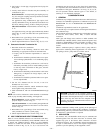
C. Combustion-Air and Vent Pipe Attachment
NOTE: All pipe joints must be watertight except attachment of
combustion-air pipe to inlet housing connection, since it may be
necessary to remove pipe for servicing.
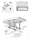
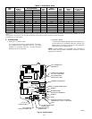
1. Attach combustion-air pipe as follows:
a. Determine location of combustion-air intake pipe con-
nection to combustion-air intake housing as shown in
Fig. 27 for application.
b. Reposition combustion-air intake housing plug fitting in
appropriate unused intake housing connection.
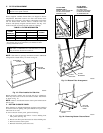
c. If required, insert perforated disk assembly (factory-
supplied in loose parts bag) in intake housing where
combustion-air intake pipe will be connected. If half disk
set is required, install with shoulder of disk against stop
in combustion-air inlet.
d. Install pipe support (factory-supplied in loose parts bag)
into selected furnace casing combustion-air pipe hole.
Pipe support should be positioned at bottom of casing
hole.
e. Insert 2-in. diameter pipe into intake housing.
NOTE: A 2-in. diameter pipe must be used within the furnace
casing. Make all pipe diameter transitions outside furnace casing.
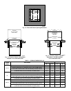
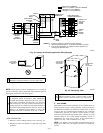
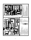
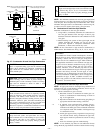
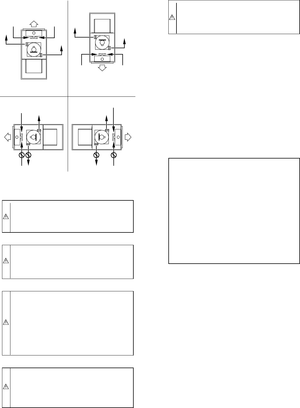
Fig. 27—Combustion-Air and Vent Pipe Connections
A96187
COMBUSTION-
AIR
COMBUSTION-
AIR
AIR
FLOW
VENT
VENT
VENT
AIR
FLOW
AIR
FLOW
AIR
FLOW
UPFLOW DOWNFLOW
HORIZONTAL-LEFT DISCHARGE HORIZONTAL-RIGHT DISCHARGE
Select 1 vent pipe connection and
1 combustion-air pipe connection.
COMBUSTION-
AIR
COMBUSTION-
AIR
COMBUSTION-
AIR
COMBUSTION-
AIR
VENT
VENT
VENT
NOTE: Select 1 vent pipe connection and
1 combustion-air pipe connection.
NOTE:
—22—
→