


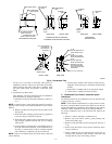
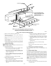
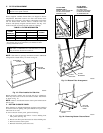
1. Remove 3 tubes connected to condensate trap.
2. Remove trap from blower shelf by gently pushing tabs
inward and rotating trap.
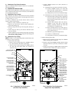
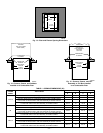
3. Remove casing hole filler cap from casing hole. (See Fig. 2
or 11.)
4. Install casing hole filler cap into blower shelf hole where
trap was removed.
5. Install condensate trap into casing hole by inserting tube
connection stubs through casing hole and rotating until tabs
snap into locking position.
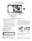
B. Condensate Trap Tubing
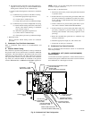
NOTE: See Fig. 11 or tube routing label on main furnace door to
check for proper connections.
1. Collector Box Drain Tube
a. Remove factory-installed plug from LOWER collector
box drain tube (blue and white striped label).
b. Install removed clamp and plug into UPPER collector
box drain tube (blue label) which was previously con-
nected to condensate trap.
c. Connect LOWER collector box drain tube (blue and
white striped label) to condensate trap. Tube does not
need to be cut.
d. Clamp tube to prevent any condensate leakage.
2. Inducer Housing Drain Tube
a. Remove factory-installed cap and clamp from LOWER
inducer housing drain connection.
b. Remove and discard UPPER (molded) inducer housing
drain tube which was previously connected to conden-
sate trap.
c. Install cap and clamp on UPPER inducer housing drain
connection where molded drain tube was removed.
d. Use inducer housing drain extension tube (violet label
and factory-supplied in loose parts bag) to connect
LOWER inducer housing drain connection to conden-
sate trap.
e. Determine appropriate length, cut, and connect tube to
condensate trap.
f. Clamp tube to prevent any condensate leakage.
3. Relief Port Tube
Refer to Pressure Switch Tubing section for connection
procedure.
C. Condensate Trap Field Drain Attachment
Refer to Condensate Drain section for recommendations and
procedures.
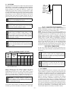
D. Pressure Switch Tubing
One collector box pressure tube (pink label) is factory connected to
the pressure switch for use when furnace is installed in UPFLOW
applications. This tube MUST be disconnected and used for the
condensate trap relief port tube. The other collector box pressure
tube (green label) which was factory connected to the condensate
trap relief port connection MUST be connected to the pressure
switch in DOWNFLOW or HORIZONTAL RIGHT applications.
NOTE: See Fig. 11 or tube routing label on main furnace door to
check for proper connections.
Relocate tubes as described below.
1. Disconnect collector box pressure tube (pink label) attached
to pressure switch.
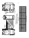
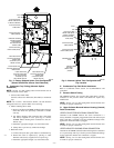
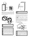
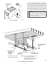
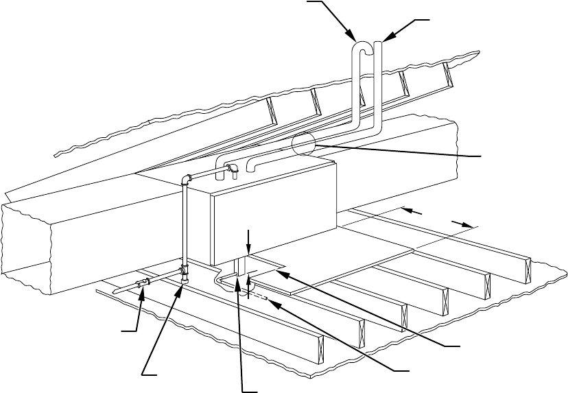
Fig. 10—Attic Location and Working Platform
A93031
COMBUSTION – AIR
INTAKE
VENT
MANUAL
SHUTOFF
GAS VALVE
SEDIMENT
TRAP
CONDENSATE
TRAP
DRAIN
ACCESS OPENING
FOR TRAP
30″ MIN
WORK AREA
A 12-IN. MIN HORIZONTAL PIPE
SECTION IS RECOMMENDED WITH
SHORT (5 TO 8 FT) VENT SYSTEMS
TO REDUCE EXCESSIVE
CONDENSATE DROPLETS FROM
EXITING THE VENT PIPE.
5
3
⁄
4
″
NOTE: LOCAL CODES MAY REQUIRE A DRAIN PAN UNDER THE
FURNACE AND CONDENSATE TRAP WHEN A CONDENSING
FURNACE IS INSTALLED ABOVE FINISHED CEILINGS.
—10—