


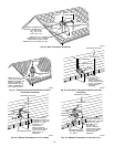

2. Cut 2 holes, 1 for each pipe, of appropriate size for pipe size
being used.
3. Loosely install elbow in bracket and place assembly on
combustion-air pipe.
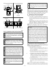
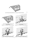
Roof terminations—Loosely install pipe coupling on prop-
erly cut vent pipe. Coupling must be positioned so bracket
will mount as shown in Fig. 30.
For applications using combustion-air pipe option, indi-
cated by dashed lines in Fig. 30, install 90° street elbow into
90° elbow, making U-fitting. A 180° U-fitting may be used.
Sidewall terminations—Install bracket as shown in Fig. 33
or 34.
For applications using vent pipe option indicated by dashed
lines in Fig. 33, rotate vent elbow 90° from position shown
in Fig. 33.
4. Disassemble loose pipe fittings. Clean and cement using
same procedures as used for system piping.
5. Check required dimensions as shown in Fig. 30, 33, or 34.
C. Concentric Vent/Air Termination Kit
1. Determine location for termination.
Consideration of the following should be made when
determining an appropriate location for termination kit.
a. Comply with all clearance requirements as stated in
Table 5.
b. Termination kit should be positioned where vent vapors
will not damage plants/shrubs or air conditioning equip-
ment.
c. Termination kit should be positioned so it will not be
affected by wind eddy (such as inside building corners)
or that may allow recirculation of flue gases, airborne
leaves, or light snow.
d. Termination kit should be positioned where it will not be
damaged by or subjected to foreign objects, such as
stones, balls, etc.
e. Termination kit should be positioned where vent vapors
are not objectionable.
2. Cut one 4-in. diameter hole for 2-in. kit, or one 5-in.
diameter hole for 3-in. kit.
3. Loosely assemble concentric vent/air termination compo-
nents together using instructions in kit.
4. Slide assembled kit with rain shield REMOVED through
hole.
NOTE: Do not allow insulation or other materials to accumulate
inside of pipe assembly when installing it through hole.
Roof terminations—Locate assembly through roof to ap-
propriate height as shown in Fig. 31.
Sidewall terminations—Locate assembly through sidewall
with rain shield positioned no more than 1-in. from wall as
shown in Fig. 32.
5. Disassemble loose pipe fittings. Clean and cement using
same procedures as used for system piping.
6. Check required dimensions as shown in Fig. 31 or 32.
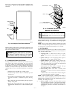
IV. MULTIVENTING AND VENT TERMINATIONS
When 2 or more 340MAV Furnaces are vented near each other,
each furnace must be individually vented. NEVER common vent
or breach vent 340MAV furnaces. When 2 or more 340MAV
furnaces are vented near each other, 2 vent terminations may be
installed as shown in Fig. 35, 36, 37, 38, or 39, but next vent
termination must be at least 36 in. away from first 2 terminations.
It is important that vent terminations be made as shown to avoid
recirculation of flue gases. Dimension "A" in Fig. 35, 36, 37, 38,
and 39 represents distance between pipes or rain shields, as
touching or 2-in. maximum separation.
CONDENSATE DRAIN
I. GENERAL
Condensate trap is shipped installed in the blower shelf and factory
connected for UPFLOW applications. Condensate trap must be
RELOCATED for use in DOWNFLOW and HORIZONTAL
applications.
Condensate trap MUST be used for all applications.
An external trap is not required when connecting the field drain to
this condensate trap.
The field drain connection (condensate trap or drain tube coupling)
is sized for 1/2-in. CPVC, 1/2-in. PVC, or 5/8-in. ID tube
connection.
Drain pipe and fittings must conform to ANSI standards and
ASTM D1785 or D2846. CPVC or PVC cement and primer must
conform to ASTM D2564 or F493. In Canada, use CSA or ULC
certified schedule 40 CPVC or PVC drain pipe, fittings, and
cement.
When a condensate pump is required, select a pump which is
approved for condensing furnace applications. To avoid conden-
sate spillage, select a pump with an overflow switch.
Furnace condensate is mildly acidic, typically in the pH range of
3.2 to 4.5. Due to corrosive nature of this condensate, a condensate
pH neutralizing filter may be desired. Check with local authorities
to determine if a pH neutralizer is required.
II. APPLICATION
The furnace, A/C, and humidifier drains may be combined and
drained together. The A/C drain must have an external, field-
supplied trap prior to the furnace drain connection. All drain
connections (furnace, A/C, or humidifier) must be terminated into
an open or vented drain as close to the respective equipment as
possible to prevent siphoning of the equipment’s drain.
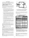
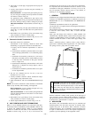
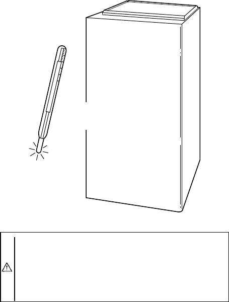
CAUTION: Unit must not be installed, operated, and
then turned off and left in an unoccupied structure during
cold weather when temperature drops to 32°F and below
unless drain trap and drain line have adequate freeze
protection. See Service and Maintenance Instructions for
winterizing procedure.
A93058
32°F MINIMUM INSTALLED
AMBIENT OR FREEZE
PROTECTION REQUIRED
—29—