


b. Reposition neoprene inducer housing outlet cap and
clamp to appropriate unused inducer housing connec-
tion. Tighten clamp.
WARNING: Inducer housing outlet cap must be in-
stalled and fully seated against inducer housing. Clamp
must be tightened to prevent any condensate leakage.
Failure to follow this warning could result in electrical
shock, fire, personal injury, or death.
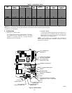
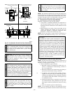
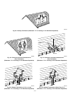
c. Install pipe support (factory-supplied in loose parts bag)
into selected furnace casing vent pipe hole. Pipe support
should be positioned at bottom of casing hole.
d. Insert 2-in. diameter pipe into inducer housing through
neoprene coupling and clamp in inducer housing.
Tighten clamp.
WARNING: Vent pipe must be installed and fully
seated against inducer housing. Clamp must be tightened
to prevent any condensate leakage. Failure to follow this
warning could result in electrical shock, fire, personal
injury, or death.
NOTE: A 2-in. diameter pipe must be used within the furnace
casing. Make all pipe diameter transitions outside furnace casing.
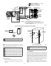
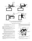
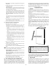
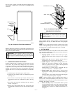
VENT EXTENSION PIPE
Some furnaces are supplied with a PVC vent extension pipe
(2-in. diameter by 12-in. long). This pipe has a built-in
channel to assist vent condensate disposal. When this vent
extension pipe is supplied, it must be used to connect the
field vent pipe to furnace inducer housing on ALL upflow
and downflow applications.
NOTE: See label on vent extension pipe for proper installation.
This pipe may be shortened if an elbow is used to connect vent
extension tube to field-installed vent pipe.
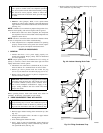
3. Working from furnace to outside, cut pipe to required
length(s).
4. Deburr inside and outside of pipe.
5. Chamfer outside edge of pipe for better distribution of
primer and cement.
6. Clean and dry all surfaces to be joined.
7. Check dry fit of pipe and mark insertion depth on pipe.
NOTE: It is recommended that all pipes be cut, prepared, and
preassembled before permanently cementing any joint.
8. After pipes have been cut and preassembled, apply gener-
ous layer of cement primer to pipe fitting socket and end of
pipe to insertion mark. Quickly apply approved cement to
end of pipe and fitting socket (over primer). Apply cement
in a light, uniform coat on inside of socket to prevent
buildup of excess cement. Apply second coat.
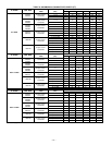
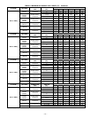
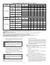
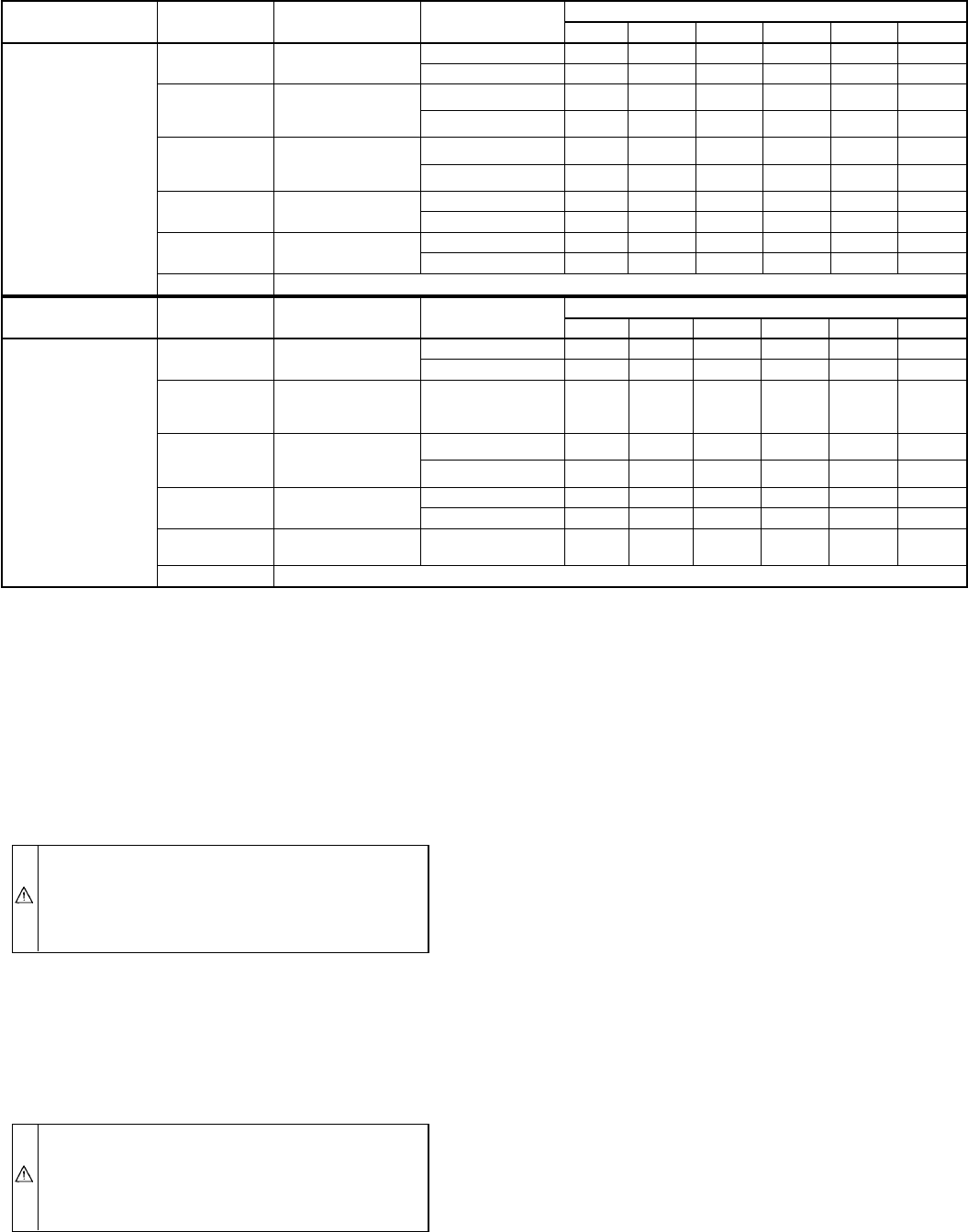
TABLE 6—MAXIMUM ALLOWABLE PIPE LENGTH (FT) Continued
ALTITUDE UNIT SIZE
TERMINATION
TYPE
PIPE DIA
(IN.)*
NUMBER OF 90° ELBOWS
123456
8001 to 9000‡
024040
036040
2 Pipe or 2-In.
Concentric
1-1/2 46 41 36 31 29 24
2 626058565553
024060
036060
048060
2 Pipe or 2-In.
Concentric
1-1/2 11 6 NA NA NA NA
2 494442373534
036080
048080
060080
2 Pipe or 2-In.
Concentric
2 3328171210NA
2-1/2 62 60 58 56 55 53
048100
060100
2 Pipe or 3-In.
Concentric
2-1/2 23 15 7 5 NA NA
3 595449443934
→060120
2 Pipe or 3-In.
Concentric
3† no disk 10 NA NA NA NA NA
4† no disk 35 30 25 20 15 10
→060140 NA
ALTITUDE UNIT SIZE
TERMINATION
TYPE
PIPE DIA
(IN.)*
NUMBER OF 90° ELBOWS
123456
9001 to 10,000‡
024040
036040
2 Pipe or 2-In.
Concentric
1-1/2 42 37 32 27 25 20
2 575553514947
024060
036060
048060
2 Pipe or 2-In.
Concentric
2 454038333129
036080
048080
060080
2 Pipe or 2-In.
Concentric
230251497NA
2-1/2 57 55 53 51 49 47
048100
060100
2 Pipe or 3-In.
Concentric
2-1/2 21 13 5 NA NA NA
3 544944393429
→060120
2 Pipe or 3-In.
Concentric
4† no disk 10 5 NA NA NA NA
→060140 NA
* Disk usage—Unless otherwise specified, use perforated disk assembly (factory-supplied in loose parts bag). If one disk is stated, separate 2 halves of perforated disk
assembly and use shouldered disk half. When using shouldered disk half, install screen side toward inlet box.
† Wide radius elbow.
‡ Vent sizing for Canadian installations over 4500 ft (1370 m) above sea level are subject to acceptance by the local authorities having jurisdiction.
NA—Not Allowed; pressure switch will not make.
NOTES:
1. Do not use pipe size greater than those specified in table or incomplete combustion, flame disturbance, or flame sense lockout may occur.
2. Size both the combustion-air and vent pipe independently, then use the larger diameter for both pipes.
3. Assume two 45° elbows equal one 90° elbow. Long radius elbows are desirable and may be required in some cases.
4. Elbows and pipe sections within the furnace casing and at the vent termination should not be included in vent length or elbow count.
5. The minimum pipe length is 5 ft for all applications.
6. Use 3-in. diameter vent termination kit for installations requiring 4-in diameter pipe.
—26—