


DIRECT VENTING
The 340MAV Furnaces require a dedicated (one 340MAV furnace
only) direct-vent system. In a direct-vent system, all air for
combustion is taken directly from outside atmosphere, and all flue
products are discharged to outside atmosphere.
I. REMOVAL OF EXISTING FURNACES FROM
COMMON VENT SYSTEMS
If furnace being replaced was connected to a common vent system
with other appliances, the following steps shall be followed with
each appliance connected to the venting system placed in opera-
tion, while any other appliances connected to the venting system
are not in operation:
1. Seal any unused openings in the venting system.
2. Inspect the venting system for proper size and horizontal
pitch as required in the National Fuel Gas Code, ANSI
Z223.1 or the CAN/CGA B149 Installation Codes and these
instructions. Determine that there is no blockage or restric-
tion, leakage, corrosion, and other deficiencies which could
cause an unsafe condition.
3. In so far as is practical, close all building doors and
windows and all doors between the space in which the
appliance(s) connected to the venting system are located
and other spaces of the building. Turn on clothes dryers and
any appliance not connected to the venting system. Turn on
any exhaust fans, such as range hoods and bathroom
exhausts, so they shall operate at maximum speed. Do not
operate a summer exhaust fan. Close fireplace dampers.
4. Follow the lighting instructions. Place the appliance being
inspected in operation. Adjust thermostat so appliance shall
operate continuously.
5. Test for draft hood equipped appliance spillage at the draft
hood relief opening after 5 minutes of main burner opera-
tion. Use the flame of a match or candle.
6. After it has been determined that each appliance connected
to the venting system properly vents when tested as outlined
above, return doors, windows, exhaust fans, fireplace damp-
ers, and any other gas-burning appliance to their previous
conditions of use.
7. If improper venting is observed during any of above tests,
the venting system must be corrected.
Vent system or vent connectors may need to be resized. For any
other appliances when resizing vent systems or vent connectors,
system or connector must be sized to approach minimum size as
determined using appropriate table found in the NFGC or NSC-
NGPIC.
II. COMBUSTION-AIR AND VENT PIPING
A. General
Combustion-air and vent pipe fittings must conform to American
National Standards Institute (ANSI) standards and American
Society for Testing and Materials (ASTM) standards D1785
(schedule-40 PVC), D2665 (PVC-DWV), D2241 (SDR-21 and
SDR-26 PVC), D2661 (ABS-DWV), F628 (schedule-40 ABS), or
F891 (PVC-DWV cellular core). Pipe cement and primer must
conform to ASTM standards D2564 (PVC) or D2235 (ABS). See
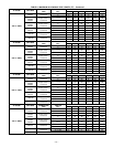
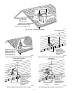
Table 6 for maximum pipe lengths and Fig. 30, 31, 32, 33, and 34
for exterior piping arrangements.
In Canada construct all combustion-air and vent pipes for this unit
of CSA or ULC certified schedule-40 PVC, PVC-DWV or
ABS-DWV pipe and pipe cement. SDR pipe is NOT approved in
Canada.
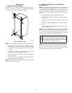
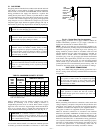
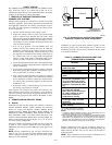
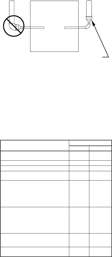
NOTE: Furnace combustion-air and vent pipe connections are
sized for 2-in. pipe. Any pipe size change should be made outside
furnace casing in vertical pipe. (See Fig. 26.) This allows proper
drainage of vent condensate.
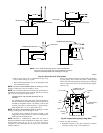
Combustion-air and vent pipes must terminate together in same
atmosphere pressure zone, either through roof or sidewall (roof
termination preferred), using accessory termination kit. See Table
5 for required clearances.
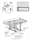
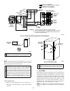
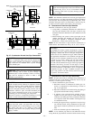
Furnace combustion-air and vent pipe connections must be at-
tached as shown in Fig. 27. Combustion-air intake plug fitting and
inducer housing alternate vent cap may need to be relocated in
some applications.
NOTE: Slope combustion-air and vent pipes a minimum of 1/4
in. per linear ft with no sags between hangers.
Fig. 26—Combustion-Air and Vent Pipe Diameter
Transition Location and Elbow Configuration
A93034
FURNACE
PIPE DIAMETER
TRANSITION IN
VERTICAL SECTION
NOT IN
HORIZONTAL
SECTION
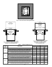
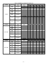
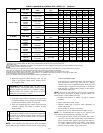
TABLE 5—COMBUSTION-AIR AND VENT PIPE
TERMINATION CLEARANCES
LOCATION
CLEARANCE (FT)
U.S.A. Canada
Above grade level or above antici-
pated snow depth
11†
Dryer vent 33
From plumbing vent stack 33
From any mechanical fresh air
intake
16
For furnaces with an input capac-
ity less than 100,000 Btuh—from
any non-mechanical air supply
(windows or doors which can be
opened) or combustion-air open-
ing
11
For furnaces with an input capac-
ity greater than 100,000
Btuh—from any non-mechanical
air supply (windows or doors
which can be opened) or
combustion-air opening
13
From service regulator vent, elec-
tric and gas meters, and relief
equipment
4* 6‡
Above grade when adjacent to
public walkway
77
* Horizontal distance.
† 18 in. above roof surface in Canada.
‡ 36 in. to electric meter in Canada only.
NOTES:
1. If installing 2 adjacent 340MAV Furnaces, refer to Multiventing and Vent
Terminations section for proper vent configurations.
2. When locating combustion-air and vent terminations, consideration must be
given to prevailing winds, location, and other conditions which may cause
recirculation of the appliance’s own flue products or the flue products of
adjacent vents. Recirculation can cause poor combustion, inlet condensate
problems, and accelerated corrosion of heat exchangers.
—21—