


9. While cement is still wet, twist pipe into socket with 1/4
turn. Be sure pipe is fully inserted into fitting socket.
10. Wipe excess cement from joint. A continuous bead of
cement will be visible around perimeter of a properly made
joint.
11. Handle pipe joints carefully until cement sets.
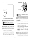
12. Support combustion-air and vent piping a minimum of
every 5 ft (3 ft for SDR-21 or -26 PVC) using perforated
metal hanging strap.
13. Slope combustion-air and vent pipes toward furnace a
minimum of 1/4 in. per linear ft with no sags between
hangers.
14. Use appropriate methods to seal openings where vent and
combustion-air pipes pass through roof or side wall.
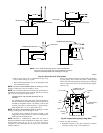
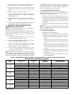
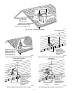
III. CONCENTRIC VENT AND COMBUSTION-AIR
TERMINATION KIT INSTALLATION
NOTE: If these instructions differ from those packaged with
termination kit, follow kit instructions.
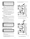
Combustion-air and vent pipes must terminate outside structure. A
factory accessory termination kit must be installed in 1 of the
installations shown in Fig. 30, 31, 32, 33, or 34. Four termination
kits are available.
1. The 2-in. termination bracket kit is for 1-in., 1-1/2 in., and
2-in. diameter 2-pipe termination systems.
2. The 3-in. termination bracket kit is for 2-1/2 in., 3-in., and
4-in. diameter 2-pipe termination systems.
3. The 2-in. concentric vent/air termination kit is for 1-in.,
1-1/2 in., 2-in., and 2-1/2 in. diameter pipe systems when
single penetration of wall or roof is desired.
4. The 3-in. concentric vent/air termination kit is for 2-1/2 in.,
3-in., and 4-in. diameter pipe systems when single penetra-
tion of wall or roof is desired.
NOTE: Shaded parts in Fig. 30, 31, 32, 33, and 34 are considered
to be termination. These components should NOT be counted
when determining pipe diameter. Roof termination is preferred
since it is less susceptible to damage, has reduced chances to take
in contaminants, and has less visible vent vapors. (See Fig. 30 or
31.) Sidewall termination may require sealing or shielding of
building surfaces with a corrosive resistance material due to
corrosive combustion products of vent system.
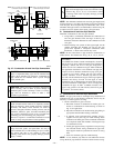
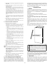
A. Extended Exposed Sidewall Pipes
Sidewall combustion-air and vent pipe terminations may be
extended beyond area shown in Fig. 33 or 34 in outside ambient by
insulating pipes as indicated in Table 7.
1. Determine combustion-air and vent pipe diameters, as
stated above, using total pipe length and number of elbows.
2. Using winter design temperature (used in load calculations),
find appropriate temperature for your application and fur-
nace model.
3. Determine required insulation thickness for exposed pipe
lengths.
NOTE: Pipe length (ft) specified for maximum pipe lengths
located in unconditioned spaces cannot exceed total allowable pipe
length as specified in Table 6.
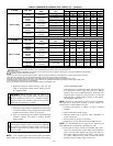
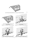
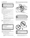
B. Two-Pipe Termination Kit
1. Determine location for termination.
Consideration of the following should be made when
determining an appropriate location for termination kit.
a. Comply with all clearance requirements as stated in
Table 5.
b. Termination kit should be positioned where vent vapors
will not damage plants/shrubs or air conditioning equip-
ment.
c. Termination kit should be positioned so that it will not be
affected by wind eddy (such as inside building corners)
or allow recirculation of flue gases, airborne leaves, or
light snow.
d. Termination kit should be positioned where it will not be
damaged by or subjected to foreign objects, such as
stones, balls, etc.
e. Termination kit should be positioned where vent vapors
are not objectionable.
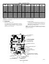
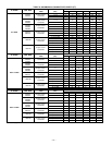
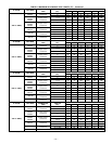
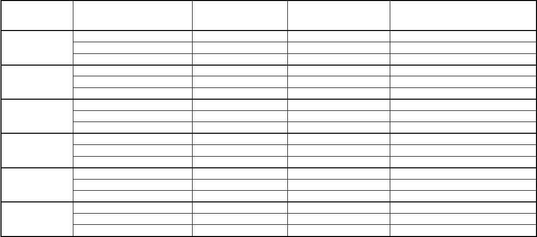
→ TABLE 7—MAXIMUM ALLOWABLE EXPOSED VENT PIPE LENGTH (FT) WITH AND WITHOUT INSULATION
IN WINTER DESIGN TEMPERATURE AMBIENT*
UNIT
SIZE
WINTER DESIGN
TEMPERATURE
(°F)
MAX PIPE
DIAMETER
(IN.)
WITHOUT
INSULATION
WITH 3/8-IN. OR
THICKER INSULATION†
040
20 1-1/2 51 70
0 1-1/2 28 70
-20 1-1/2 16 70
060
20 2 65 70
0 2 35 70
-20 2 20 70
080
20 2-1/2 70 70
0 2-1/2 47 70
-20 2-1/2 28 70
100
20 3 70 70
0 3 50 70
-20 3 28 70
120
20 4 70 70
0 4 48 70
-20 4 23 70
140
20 4 70 70
0 4 57 70
-20 4 30 70
* Pipe length (ft) specified for maximum pipe lengths located in unconditioned spaces. Pipes located in unconditioned space cannot exceed total allowable pipe length as
specified in Table 6.
† Insulation thickness based on R value of 3.5 per in.
—27—
→
→