


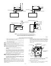
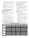
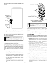

See Fig. 40 for example of possible field drain attachment using
1/2-in. CPVC or PVC tee for vent and A/C or humidifier drain
connection.
Outdoor draining of the furnace is permissible if allowed by local
codes. Caution should be taken when freezing ambient may freeze
drain pipe and prohibit draining.
WARNING: Caution should be taken to prevent drain-
ing where slippery conditions may cause personal inju-
ries. Excessive condensate draining may cause saturated
soil conditions which may result in damage to plants.
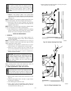
III. CONDENSATE DRAIN PROTECTION
Freezing condensate left in condensate trap and drain line may
cause cracks, and possible water damage may occur. If freeze
protection is required, use condensate freeze protection accessory
or equivalent 3 to 6 watt per ft at 120v and 40°F self-regulating,
shielded, and waterproof heat tape. See Installation Instructions
supplied with accessory or heat tape manufacturer’s recommenda-
tions.
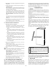
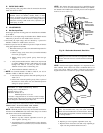
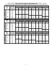
1. Fold heat tape in half and wrap on itself 3 times.
2. Locate heat tape between sides of condensate trap back.
(See Fig. 41.)
3. Use wire ties to secure heat tape in place. Wire ties can be
positioned in notches of condensate trap sides. (See Fig.
41.)
4. Wrap field drain pipe with remaining heat tape, approxi-
mately 1 wrap per ft.
5. When using field-supplied heat tape, follow heat tape
manufacturer’s instructions for all other installation guide-
lines.
SEQUENCE OF OPERATION
CAUTION: Furnace control must be grounded for
proper operation, or control will lock out. Control is
grounded through green wire routed to gas valve and
burner box screw.
Using schematic diagram, follow sequence of operation through
different modes. (See Fig. 24.) Read and follow wiring diagram
carefully.
NOTE: If 115-v power supply to furnace or blower access panel
switch is interrupted during a call for heat, blower operates for 90
sec when power is restored before heating cycle is resumed.
I. HEATING MODE
When wall thermostat calls for heat, R-W circuit closes. Furnace
control performs a self-check, verifies pressure switch contacts are
open, and starts inducer motor.
1. Prepurge period—As inducer motor comes up to speed,
pressure switch contacts close to begin a 15-sec prepurge
period.
2. Ignitor warm up—At end of prepurge period, ignitor is
energized for a 17-sec ignitor warm-up period.
3. Ignition sequence—When ignitor warm-up period is com-
pleted, gas valve opens, permitting gas flow to burners
where it is ignited. After 5 sec, ignitor is de-energized and
a 2-sec flame-sensing period begins.
HUM terminal on control center is energized with gas
valve. See Accessories — Humidifier section.
4. Flame sensing—When burner flame is sensed, control
begins blower on delay period and continues holding gas
valve open.
If burner flame is not sensed, control center de-energizes
gas valve and ignition sequence is repeated.
NOTE: Ignition sequence repeats 3 additional times before a
lockout occurs. Lockout automatically resets after 3 hr or can be
manually reset by turning off 115v (not at thermostat) for 3 sec
minimum, then turning it on again.
5. Blower on delay—Sixty sec after burner flame is proven
(40 sec if jumper has been cut for 140 size unit in downflow
orientation), blower motor is energized on heating speed.
Simultaneously, electronic air cleaner terminal EAC-1 is
energized.
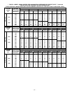
Fig. 40—Example of Field Drain Attachment
A94054
OPEN STAND
PIPE FOR
A/C OR
HUMIDIFIER
DRAIN
TEE
TO OPEN
DRAIN
Fig. 41—Condensate Trap Heat Tape
A93036
CONDENSATE TRAP
WIRE TIE(S)
HEAT TAPE
(3 WRAPS MINIMUM)
—31—
→