


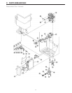

IGI – 9. Removal of the Gas Valve Assembly:
CAUTION
120 volt potential exposure. Isolate the appliance and
reconfirm power has been disconnected using a multi-
meter.
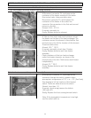
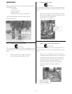
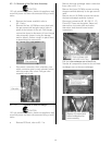
a. Remove the burner manifold, refer to
IGI - 8 a,b,c.
b. Remove the four (4) Phillips screws that hold
the gas connection and gas control valve in
place at the bottom of the unit. Pull the gas
connection down to disconnect it from the gas
valve assembly. Inspect o-ring for damage
and/or defects. Ensure o-ring is in place when
re-assembling this connection.
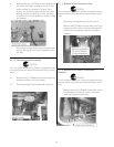
c. Disconnect connectors from solenoids, note
which connector goes to each solenoid, alone
with the proper wire colors. Pull gas valve
assembly out of unit.
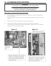
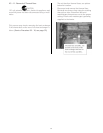
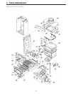
IGI – 10. Removal of Heat Exchanger:
CAUTION
120 volt potential exposure. Isolate the appliance and
reconfirm power has been disconnected using a multi-
meter.
a. Remove PCB unit, refer to IGI - 2 a.
b. Remove the heat exchanger water connection
lines, refer to IGI - 3 a.
c. Remove the three (3) Phillip screws securing
the gas manifold assembly to the gas control
valve.
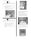
d. Remove the six (6) Phillip screws that secure
the heat exchanger assembly in place.
e. Disconnect connectors B1, B5, B6, C1, C3,
F1and F8. These are the igniter, flame rod,
thermo-fuse, hot water inlet and outlet
thermistor, and the anti-freeze heater
connections.
f. Pull the heat exchanger out of the heater.
g. Transfer all components found on the old heat
exchanger over to the new exchanger.
52