


32
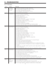
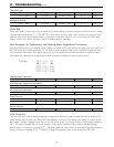
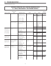
Nature of Fault
Examination
Point Diagnostic Point Values Y/N Action
Service
Procedure
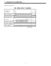
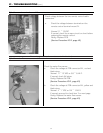
2. Measure the voltage
at connector F with
appliance power supply
on.
F – Black
~
White
100
~
120 VAC
F
7
– Blue
~
Brown
100
~
120 VAC
Are values within
those specified at
left.
Yes
No
Go to A – (7)
Replace
transformer
IGI – 7
7. Check remotes (s)
(where connected.)
Measure voltage
between remote control
terminals at D.
11
~
13 VDC Digital Yes
No
Check cable
for shorts or
broken wires.
Replace
remote
control.
Replace PCB.
IGI – 2
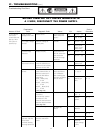
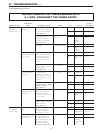
B. Digital monitor
lights up, but
combustion does
not commence.
(when remotes
are connected).
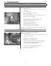
1. Check water flow
sensor.
1. Measure voltage
between red
~
black of
connector B
4
.
(See page 37)
2. Measure voltage
between yellow
~
black
at connector B
4
.
(See page 37)
11
~
13 VDC
4
~
7 VDC
Yes
No
Yes
No
Go to B–1-2
Replace PCB.
Go to B - 2
Replace water
flow sensor.
IGI – 2
IGI – 3
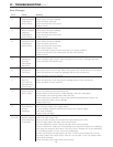
Error code "72"
displayed on the
digital monitor.
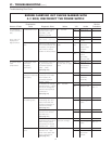
2. Check flame rod # Measure resistance
between flame rod
terminal C
1
and earth.
(See page 38)
Resistance > 1MΩ? Yes
No
Replace PCB
Replace flame
rod
IGI – 2
Error code "32"
displayed on the
digital monitor.
3. Check outgoing
water temperature
thermistor.
# Disconnect connector
B5 and measure
resistance.
Open circuit: > 1MΩ
Short circuit: < 1Ω
(See page 38)
Are values as shown
at left?
Yes
No
Replace water
temperature
thermistor.
Go to B - 4
IGI – 6
Error code "61"
displayed on the
digital monitor.
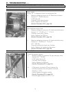
4. Check
combustion fan.
1. Check motor.
Measure voltage
between black
~
red at
connector A
1
.
(See page 39)
6
~
45 VDC (Fan on)
0 VDC (Fan off)
Yes
No
Go to B – 5-2
Replace PCB IGI – 2
2. Check fan rotation
sensor. Measure voltage
between black
~
yellow
at connector A
1
.
(See page 39)
11
~
13 VDC Yes
No
Go to B – 4-3
Replace PCB IGI – 2
3. Measure voltage
between black ~ white
of connector A
1
.
(See page 39)
6
~
45 VDC Yes
No
Go to B – 5
Replace fan IGI – 5
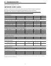
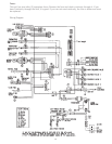
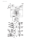
VI - TROUBLESHOOTING (cont.)
Troubleshooting Flow Chart
BEFORE CARRYING OUT CHECKS MARKED WITH
A # SIGN, DISCONNECT THE POWER SUPPLY.