


39
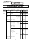
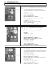
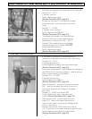
Motor check.
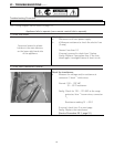
If error “61” is displayed, check the combustion fan.
a. Measure voltage at connector A1. Black and red wires.
Normal: 6 ~ 45 VDC (Fan on)
0 VDC (Fan off)
If normal, check item b below.
Faulty: Replace the PCB unit.
(Service Procedure IGI-2, page 49)
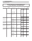
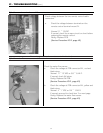
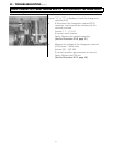
Fan revolution sensor check.
b. Measure voltage at connector A1, black and yellow wires.
Normal: 11 ~ 13 VDC or 3.1 ~ 3.7 K Ω
If normal, check item c below.
Faulty: Replace the PCB unit.
(Service Procedure IGI-2, page 49)
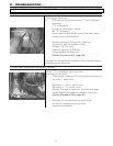
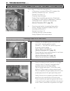
c. Measure voltage at connector A1, black and white wires.
Normal: 6 ~ 45 VDC or 9 ~ 9.4 K Ω
(33 ~ 400 Hz.)
If normal, proceed to check item 5 below.
Faulty: Replace the combustion fan motor.
(Service Procedure IGI-5, page 50)
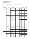
4) Is the combustion fan motor normal ?
5) Is the ignition module operating normally ?
.
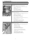
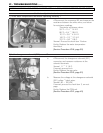
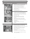
Check the sparker module.
a. Measure voltage at connector F8, grey and grey wires.
Normal: 90 ~ 110 VAC
0 VDC (when fan is off)
If normal, check b below.
Faulty: Replace the PCB unit.
(Service Procedure IGI-2, page 49)
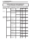
b. # Disconnect connector F8, and measure the
resistance between the two sparker terminals.
Normal: > 1 M Ω
Faulty: Replace the igniter module.
(Service Procedure IGI-5, page 50)
Electrode gap should be 3/16” to 1/4" .
VI - TROUBLESHOOTING (cont.)
BEFORE CARRYING OUT CHECKS MARKED WITH A # SIGN, DISCONNECT THE POWER SUPPLY.