


35
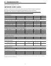
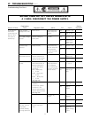
Nature of Fault
Examination
Point Diagnostic Point Values Y/N Action
Service
Procedure
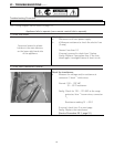
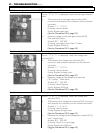
2. Measure voltage
between orange (+) and
grey (-) of the water flow
servo connector B
2
.
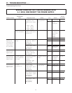
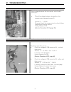
3. Measure voltage
between brown
~
grey
of water flow servo
connector B
2
(Don not
turn water on)
(See page 44)
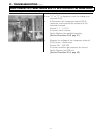
4. Measure voltage
between yellow
~
grey
of the water flow servo
connector B
2
(Do not
turn water on)
(See page 44)
11
~
13 VDC
4
~
6 VDC
4
~
6 VDC
Yes
No
Yes
No
Yes
No
Go to 4-3
Replace PCB
Go to D-4-4
Replace water
flow servo
sensor.
Normal
Replace water
flow servo
sensor.
IGI – 2
IGI – 3
IGI – 3
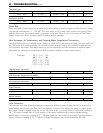
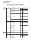
E. Anti-frost
heater does not
work.
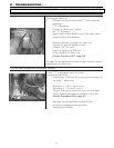
1. check anti-frost
heater.
1. # Disconnect
connector F
4
and F
5
measure resistance
across each of the
heating elements. (white
wires)
(See page 45)
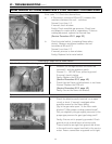
2. # Read resistance of
the heating element that
is mounted on the front
of the heat exchanger.
(white wires)
(See page 45)
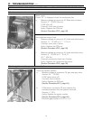
3. Read resistance of
heating elements on the
heat exchanger outlet
hot water line.
(See page 45)
348
~
375Ω
100
~
11 0 Ω
33
~
39Ω
Yes
No
Yes
No
Yes
No
Go to E-1-2
Replace Anti-
frost sensing
switch.
Go to E-2
Replace Anti-
frost heater
that is
defective.
Go to E-2
Replace Anti-
frost heater
that is
defective.
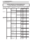
2. Check frost
sensing switch
# Disconnect connector
F
2
and measure across
the bi-metal sensing
switch located on the
upper right hand of the
heat exchanger. check
this switch at
temperatures below 37
°F. You can place an ice
cube against the switch
to activate it.
(See page 45)
Is resistance <1Ω
after applying ice to
this switch for five
minutes?
Yes
No
Check wiring
Replace Anti-
frost sensing
switch.
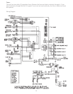
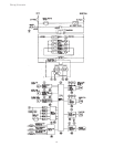
VI - TROUBLESHOOTING (cont.)
Troubleshooting Flow Chart
BEFORE CARRYING OUT CHECKS MARKED WITH
A # SIGN, DISCONNECT THE POWER SUPPLY.