


33
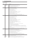
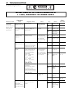
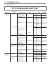
Nature of Fault
Examination
Point Diagnostic Point Values Y/N Action
Service
Procedure
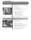
Error code "11"
displayed on
digital monitor.
5. Check ignition
module.
1. Measure voltage
between grey
~
grey of
connector F
8
(sparker).
(See page 39)
2. # Remove connector
F
8
and measure the
resistance between
sparker and terminals.
(See page 39)
90
~
110 V AC
Is resistance >
1MΩ?
Yes
No
Yes
No
Go to B-5-2
Replace PCB
Go to B-5-3
Adjust/
Replace
ignition
module
IG2 – 2
IGI – 4
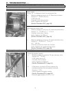
3. Check if unit is
sparking.
Is the ignition
module sparking?
Yes
No
Go to B-6
Adjust/
Replace
electrode
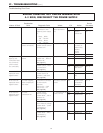
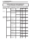
6. Check main gas
solenoid valve (SV0)
Error code 71
1. # Disconnect the main
solenoid valve connector
E from the PCB, and
measure the resistance
between pink
~
black
(SV0)
2. Measure voltage
between pink
~
black of
SV0 connector.
(See page 40)
1.7
~
2.1KΩ
80
~
100 VDC
Yes
No
Yes
No
Go to B-6-2
Replace gas
valve
Go to B-7
Replace PCB
IGI – 9
IGI – 2
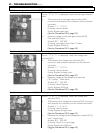
7. Check solenoid
valve (SV1)
1. # Disconnect
connector E from the
PCB. Measure resistance
between yellow
~
black
of (SV1).
2. Measure voltage
between yellow
~
black
of SV1 connector.
(See page 40)
1.7
~
2.1KΩ
80
~
100 VDC
Yes
No
Yes
No
Go to B-7-2
Replace gas
valve
Go to B-8
Replace PCB
IGI – 9
IGI – 2
8. Check
changeover solenoid
valve (SV2)
1. # Disconnect
connector E from the
PCB. And measure
resistance between blue
~
black (SV2)
2. Measure the voltage
between blue
~
black or
SV2 connector.
(See page 40)
1.7
~
2.1KΩ
80
~
100 VDC
Yes
No
Yes
No
Go to B-8-2
Replace gas
valve
Go to B-9
Replace PCB
IGI – 9
IGI – 2
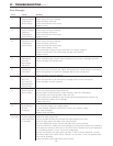
Error code "14"
displayed on
digital monitor
9. Check thermal
fuse
10. Check overheat
(remaining flame) bi-
metal switch
1. # Disconnect
connector B
3
and C
3
measure resistance
between red
~
red.
2. # Disconnect OHS
(remaining flame) bi-
metal switch festoon
terminal B
3
and C
3
, and
measure resistance
between terminal on
switch. (See page 42)
Is resistance < 1Ω?
Is resistance < 1Ω?
Yes
No
Yes
No
Go to B-10
Replace
thermal fuse
Replace PCB
Replace
remaining
flame bi-metal
switch
IGI – 11
IGI – 2
VI - TROUBLESHOOTING (cont.)
Troubleshooting Flow Chart
BEFORE CARRYING OUT CHECKS MARKED WITH
A # SIGN, DISCONNECT THE POWER SUPPLY.