


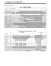
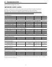
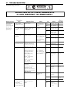

31
Nature of Fault
Examination
Point Diagnostic Point Values Y/N Action
Service
Procedure
A. The LED on
the remote
control does not
light up, when
the system is
powered up
1. Do you have
voltage to the unit?
Power source Do you have 120
VAC at the power
supply?
Yes
No
Go to A – (2)
Plug in cord
2. Is supply voltage
correct?
Measure voltage at
power point.
120 VAC Yes
No
Go to A – (3)
Check power
supply circuit.
Check fuses.
3. Check surge
protector.
Inspect visually Do you have 120
volts AC across the
blue and brown
wires at the surge
protector?
Yes
No
Go to A – (4)
Go to A – (5)
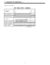
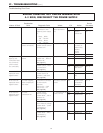
4. Check both 3
amp electrical fuses.
# Disconnect and
measure resistance to
confirm if fuse is blown.
Normal < than 1 MΩ
Is fuse blown? Yes
No
Go to A – (5)
replace fuse
Go to A – (6)
5. Check for short
circuits.
1. Measure resistance of
each solenoid valve. #
Remove connector E
from the PCB before
measuring.
Pink
~
Black (SV0)
1.7
~
2.1KΩ
Yellow
~
Black (SV1)
1.7
~
2.1KΩ
Brown
~
Black (SV2)
1.7
~
2.1KΩ
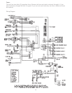
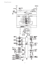
(See page 40)
1. Measure the
resistance.
# Disconnect sparker
connector F
8
and
measure the resistance
between both terminals.
(See page 39)
3. Check wiring.
Are valves within
those specified at
left? # Measure
after checking that
there are no broken
wires or shorts.
Is resistance >1MΩ ?
Are there any
shorts?
Yes
No
Yes
No
Yes
No
Go to
A – (6) - 2
Replace gas
valve.
Go to
A (5 – 3)
Replace
sparker.
Rectify
/Replace
Replace PCB
IGI – 9
IGI – 4
IGI – 2
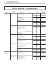
6. Check to ensure
you have 120 VAC
across both
terminals feeding
the surge protector.
1. Measure voltage at
the blue and brown
wires.
100
~
120 VAC Yes
No
Go to A (6 – 2)
Check for
proper voltage
to unit.
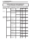
VI - TROUBLESHOOTING (cont.)
Troubleshooting Flow Chart
BEFORE CARRYING OUT CHECKS MARKED WITH
A # SIGN, DISCONNECT THE POWER SUPPLY.