


V - SEQUENCE OF OPERATION
The preset temperature is selected at one of the remotes controls (where fitted). Where no remote
control is fitted , the default temperature can be set at 108, 120, 130, 140, 150, 160, 170, or 180°F.
To select one of the above temperatures as your default setting, you MUST obtain written permission
and training (Contact your technical service group).
When the unit is first plugged into 120 volts, the PCB assumes an incoming water temperature of
77°F. This prevents the appliance from starting in “High fire” and producing very hot water the first
time it is used.
The data used to determine the outgoing water temperature, initially, is incoming water flow and the
remote control pre-set temperature.
From the incoming water flow and remote control pre-set temperature data, the CPU is able to
determine a suitable gas rate to initiate appliance operation once a hot water tap opens.
The calculation of temperature rise and water flow is called simulation feed-forward.
The water heater calculates incoming water temperature by subtracting the theoretical temperature
rise from the outgoing hot water temperature to establish the correct gas flow.
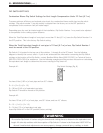
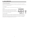
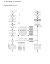
When a hot water tap is opened, water begins to flow through the water heater. The turbine in the
water flow sensor begins to revolve. The revolution speed is proportional to the water flow. A sensor
located inside the device relays information in the form of magnetic pulses to the main PCB to
determine whether or not water is flowing, and also, the volume of water flowing. When a
predetermined water flow is sensed, the ignition sequence begins.
The combustion fan pre-purges the combustion chamber. A rev counter on the combustion fan
indicates the fan rpm to the main PCB. When the pre-purge cycle is completed, the PCB controls the
fan rpm by varying the DC voltage to the fan motor. This maintains the correct air/gas ratio
throughout the time the water heater is in use and ensures proper combustion.
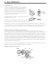
The gas is ignited by direct spark and the flame is sensed by the flame rod. The opening degree of
the modulating valve is determined by the combustion fan speed.
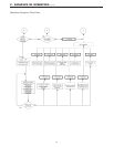
The changeover valve directs gas to one side or both sides of the burner. At the point where the
changeover valve opens or closes the modulating valve is instantly re-adjusted by the PCB to
compensate for the change in the number of burners in use. From the information provided by the
water flow sensor and the water temperature thermistor, the PCB determines how much gas is
required to heat the water to the temperature selected on the remote control.
The PCB is programmed to provide the maximum volume of water possible at a given temperature
rise. As the water flow from the tap is increased, the PCB increases the gas and air flow to the burner.
19