


PILOT ASSEMBLY INSPECTION,
CLEANING AND REPLACEMENT
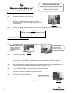
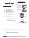
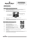
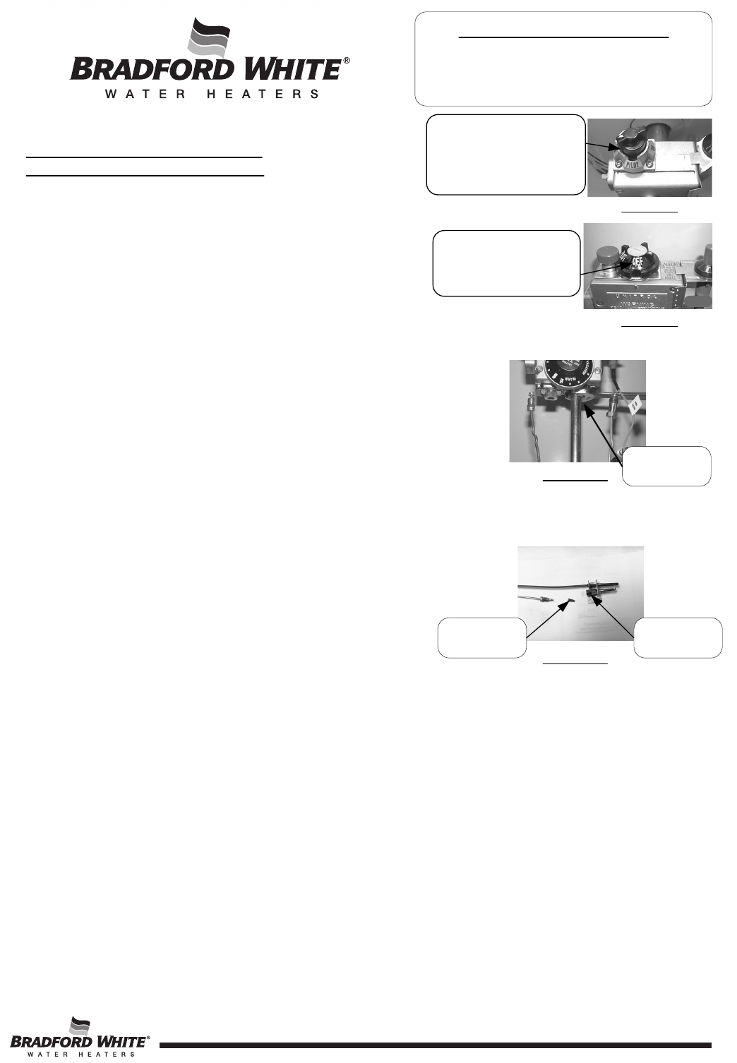
Step 1. Turn off gas supply to water heater. Rotate knob
of gas control to “OFF” position.
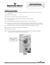
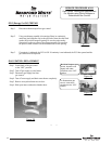
Step 2. Remove outer jacket door.
Step 3. Slide open inner combustion chamber door.
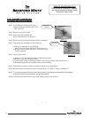
Step 4. Disconnect thermocouple, pilot tube,
and feedline from gas control.
NOTE: Feedline nut for natural gas control
uses right hand threads, LP control uses left hand thread.
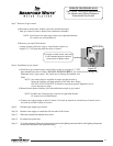
Step 5. Remove burner assembly from combustion chamber.
Step 6. Remove pilot assembly from feedline.
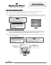
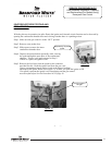
Step 7. Inspect pilot for the following:
a) Primary air openings for blockage. Must be free from any
debris (dirt, lint, etc).
b) Kinks or cracks in the pilot tube. If found,
the pilot must be replaced.
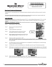
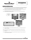
Step 8. Inspect pilot orifice:
a) Remove ½" nut from bottom of pilot assembly.
b) Remove pilot tube and pilot orifice.
c) inspect pilot orifice for blockage, must be cleaned or replaced.
SERVICE PROCEDURE AG-II
Pilot Assembly Inspection, Cleaning
and Replacement For Models Using White
Rodgers or Robertshaw Gas Control
Step 9. Install pilot assembly to feedline, secure with screw from step 6.
Step 10. Re-Install burner assembly into combustion chamber, connect feedline, pilot tube and thermocouple
to gas control.
Step 11. Slide inner combustion chamber door closed and re-attach outer jacket door.
Step 12. To resume operation follow the instructions located on the lighting instruction label or the lighting
instructions located in the installation and operation manual.
Page 9
Primary Air
Opening
R
For White Rodgers gas
control, depress knob
slightly and rotate
clockwise to the “OFF”
position.
For Robertshaw gas
control, rotate knob
clockwise to the “OFF”
position.
Pilot Orifice
Feedline Nut
Figure 8
Figure 9
Figure 10
Figure 11
9