


SERVICE PROCEDURE AG-III
Honeywell Gas Control and Thermowell
Replacement
HONEYWELL GAS CONTROL ASSEMBLY TO THERMALWELL
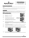
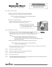
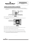
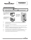
Step 1. Install threaded end of thermowell into water heater. When tight, be sure thermowell flange is
positioned so that thermowell relief opening is in the 6 o’clock position for proper control alignment
(see Figure 35).
Figure 35
Thermowell
flange slots
Route wire through
relief opening
Step 2. Route lead wires through the relief opening (see Figure 35).
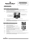
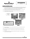
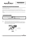
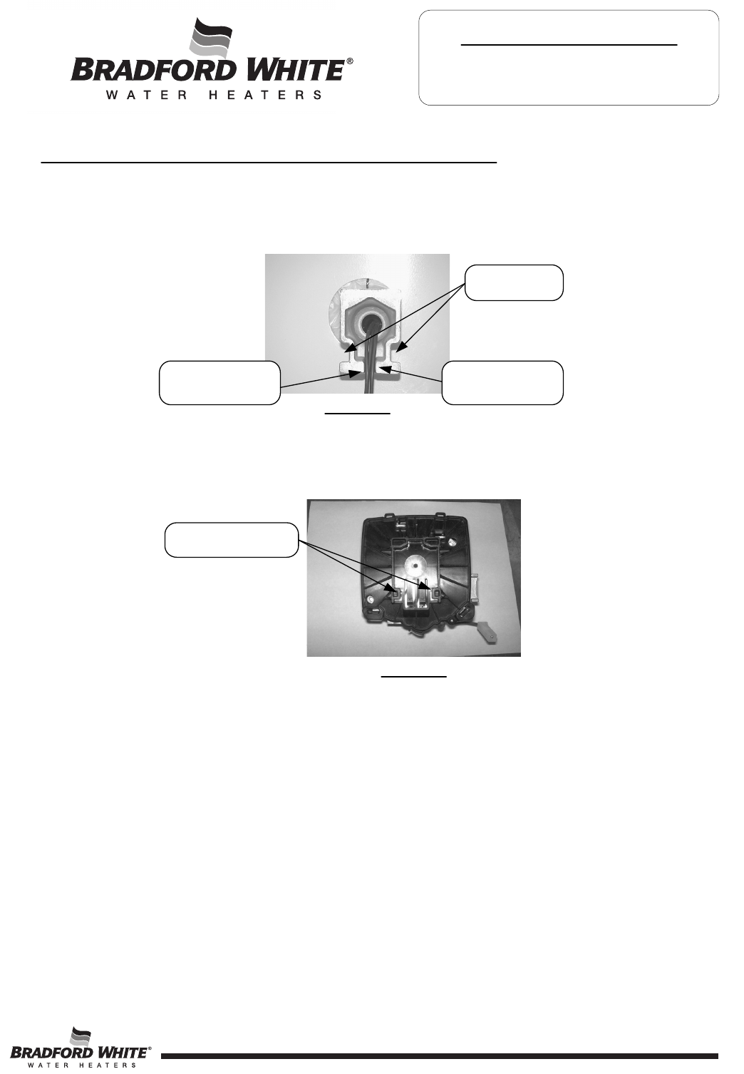
Step 3. Align slots located on the thermowell flange with tabs located on the back of the gas control
(see Figure 36).
Figure 36
Gas control tabs
Step 4. Carefully push the gas control back onto the thermowell flange.
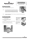
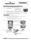
Step 5. Install burner assembly and reconnect pilot tubing and main burner feed line to gas control.
Step 6. Reconnect wire harness and igniter wire to the gas control.
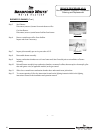
Step 7. Resume water supply to water heater and check for leaks. Be sure tank is full of water.
Step 8. Reconnect the gas supply to gas control. Check for gas leaks using a soapy water solution.
Step 9. To resume operation follow the instructions located on the lighting instruction label or the lighting
instructions located in the installation and operation manual.
Page 19
6 o’clock position
19