


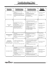
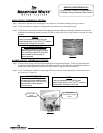
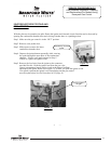
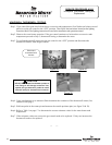

Figure 6
OPEN CIRCUIT THERMOPILE TESTING
Step 1. Disconnect red and white thermopile wires from the wire harness leading to the gas control.
Step 2. Using a multimeter capable of reading millivolts, check across thermopile leads.
Step 3. Following the instructions located on the lighting instruction label or the lighting instructions located in the
installation and operation manual, proceed to light the pilot and allow the gas control to operate for three
minutes.
Step 1. Closed circuit testing is the preferred method for testing the thermopile. Following the instructions
located on the lighting instruction label or the lighting instructions located in the installation and operation
manual, proceed to light the pilot and allow the control to operate for three minutes.
Step 2. Using a multimeter capable of measuring millivolts, measure across thermopile connections at the
gas control (see Figure 6).
CLOSED CIRCUIT THERMOPILE TESTING
Thermopile
Connections at gas
control
Page 7
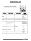
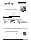
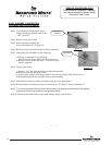
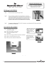
Figure 5
Gas Control
Knob
SERVICE PROCEDURE AG-I
Thermocouple Testing and Replacement
For Models Using Honeywell Gas Control
NOTE:
It may be necessary to hold the gas
control knob down in the “PILOT” position
continuously throughout this test.
NOTE:
It may be necessary to hold the gas
control knob down in the “PILOT” position
continuously throughout this test.
In a CLOSED CIRCUIT test:
Any reading over 300 millivolts
indicates good thermopile output.
For readings under 300 millivolts
replacement of thermopile is
recommended.
In an OPEN C IRCUIT test:
Any reading over 400 millivolts
indicates good thermopile output.
For readings under 400 millivolts
replacement of thermopi le is
recommended.
7