


See SERVICE PROCEDURE AG-II
THERMOCOUPLE TESTING
MAGNET ASSEMBLY TESTING (White Rodgers Control)
Page 13
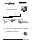
Step 1. Following the lighting instruction label on the heater, proceed to light the pilot and allow to operate for
three minutes. If the pilot will not stay lit, hold the pilot button (located on the combination
thermostat/gas valve) down during this test
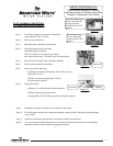
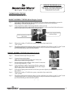
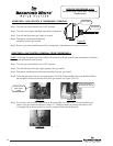
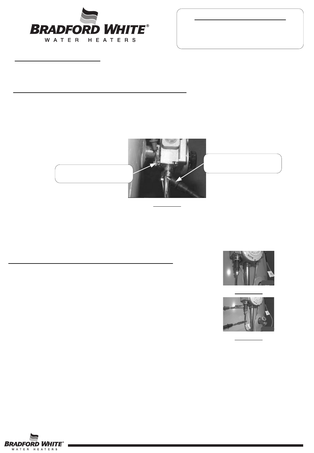
Step 2. Using a multimeter capable of measuring millivolts, connect one lead
using an alligator clip to the copper sheath of the thermocouple, use the second lead of the multi meter to
probe the top terminal located at the back of the gas control.
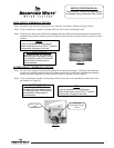
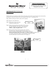
Step 6. With a meter reading of 13 millivolts or greater, rotate knob of gas control to the
“OFF” position.
Step 7. The magnet should remain closed for a drop of at least 6 millivolts. You will here a “snap” or “click” sound
when the magnet opens, if you hear this sound prior to a drop of 6 millivolts, the magnet is out of
specification and the gas control should be replaced.
MAGNET ASSEMBLY TESTING (Robertshaw Control)
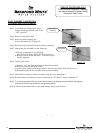
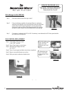
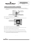
Step 1. Disconnect thermocouple from gas control.
Step 2. Connect a thermocouple adaptor
(BWC P/N 239-44642-00, Robertshaw P/N 75036) at the
thermocouple location in the gas control.
Step 3. Reconnect thermocouple to adaptor. Make certain all connections
are tight (finger tight plus ¼” turn).
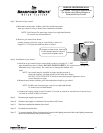
Step 4. Using a multimeter capable of measuring millivolts, connect one
alligator clip to the set screw of the adaptor and the other alligator
clip to copper portion of the thermocouple.
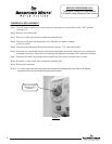
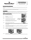
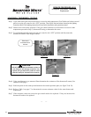
Step 5. Following the lighting instruction label on the heater, proceed to light the pilot and allow to operate for
three minuets.
Step 6. With a meter reading of 13 millivolts or greater, rotate knob of gas control to the
“OFF” position.
Step 7. The magnet should remain closed for a drop of at least 6 millivolts. You will here a “snap” or “click” sound
when the magnet opens, if you hear this sound prior to a drop of 6 millivolts, the magnet is out of
specification and the gas control should be replaced.
Figure 21
Figure 22
Figure 20
Probe top terminal on back of
gas control
Alligator clip to copper sheath
of thermocouple
SERVICE PROCEDURE AG-III
Gas Control Testing and Replacement
For Models using White Rodgers or
Robertshaw Gas Control
13