


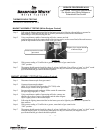
Figure 7
SERVICE PROCEDURE AG-I
Thermopile Testing and Replacement
For Models Using Honeywell Gas Control
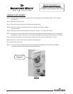
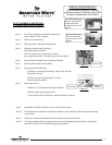
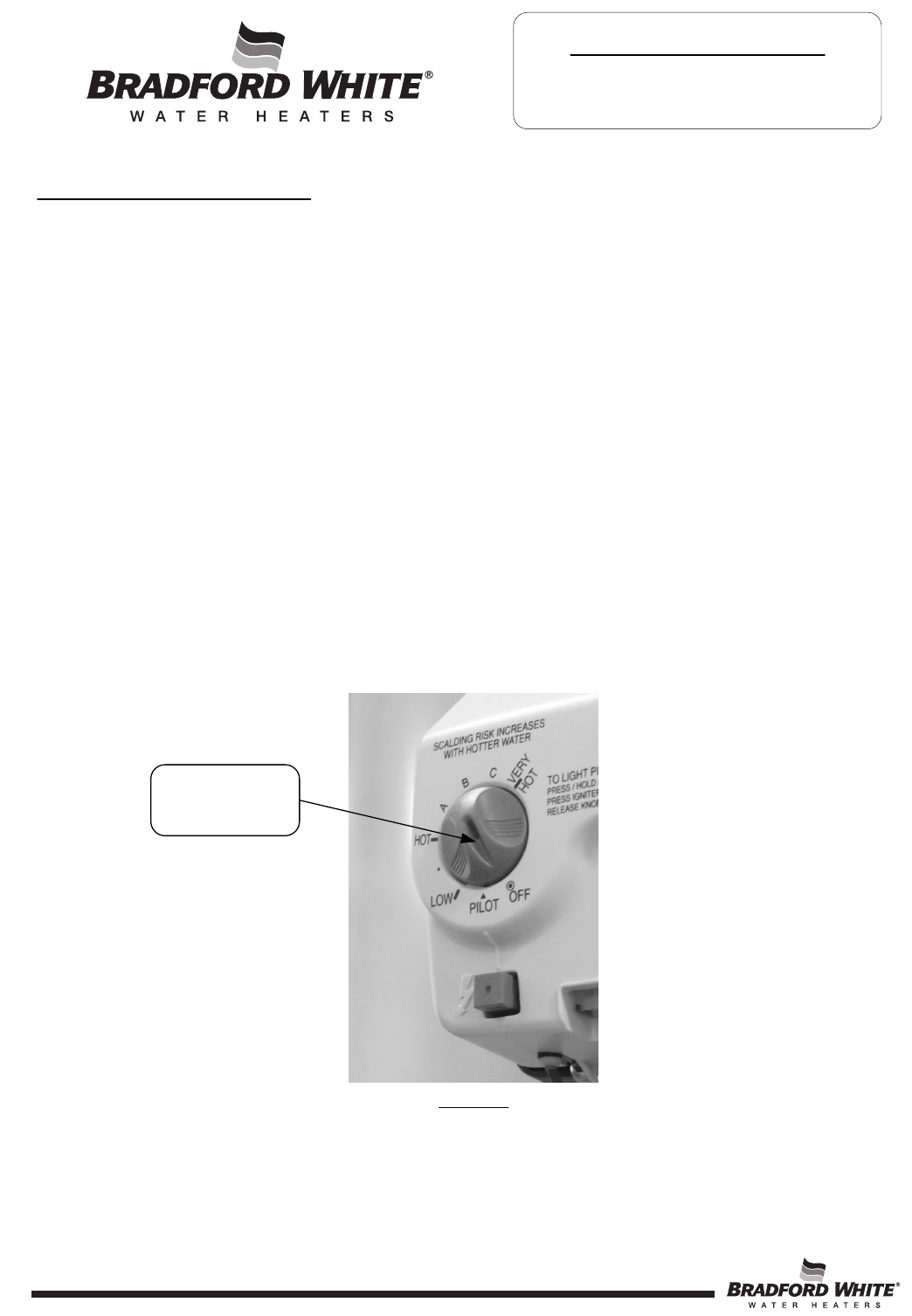
Step 1. Turn off the gas supply to the water heater by rotating the gas control knob to the “OFF” position
(see Figure 7).
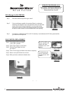
Step 2. Remove outer jacket door.
Step 3. Remove or slide open the inner combustion chamber door.
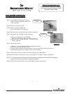
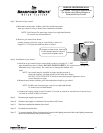
Step 4. Disconnect red and white thermopile wires from the wire harness leading
to the gas control.
Step 5. Disconnect the thermopile from the pilot bracket using a 7/16” open-end wrench.
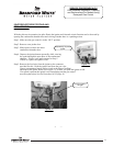
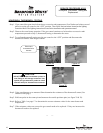
Step 6. Install the new thermopile into the pilot bracket and tighten the threads using care not to damage the
thermopile lead wires. Route new wires through the appropriate opening in the combustion chamber.
Step 7. Reconnect the lead wires being careful to match the colors (red to red and white to white).
Step 8. Reinstall, or slide closed, inner combustion chamber door.
Step 9. Replace the outer door.
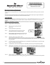
Step 10. To resume operation follow the instructions located on the lighting instruction label or the lighting
instructions located in the installation and operation manual.
Page 8
THERMOPILE REPLACEMENT
Gas Control Knob
(Shown in OFF
position)
8