


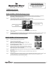
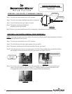
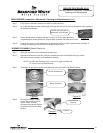


Step 3. Fully inspect combustion chamber for debris or carbon build up.
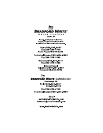
Step 4. Be certain that thermocouple or thermopile, and pilot tube are routed correctly through the relief opening in
the combustion chamber.
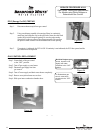
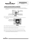
Step 5. Burner should operate as adjusted in step 2 on page 20, if not, repeat procedure
compensating air shutter position for proper burner operation with inner door closed.
Step 6. It may be necessary to clean main burner or main burner orifice to achieve proper burner operation. If
cleaning is required proceed to burner cleaning procedure below.
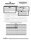
MAIN BURNER: Inspection, Adjustment, Cleaning and Replacement (cont.)
SERVICE PROCEDURE AG-IV
Burner Operation Inspection, Adjustment
Cleaning and Replacement
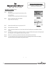
Position thermocouple or
thermopile, and pilot tube.
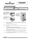
BURNER CLEANING (Steel & Cast Iron)
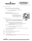
Step 1. Slide open or remove inner combustion chamber door.
Step 2. Disconnect main burner feed line, pilot tube, and thermocouple or thermopile from gas control
and remove burner assembly from combustion chamber.
NOTE: Feedline nut for natural gas control uses right hand threads,
LP control uses left hand threads.
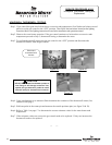
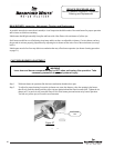
Step 3. Thoroughly inspect burner surface area and burner ports and remove any debris build up.
Page 21
Figure 39
Figure 41
Figure 40
Figure 42
Burner Surface Area
Burner Port Area
Figure 43
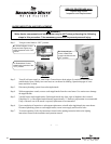
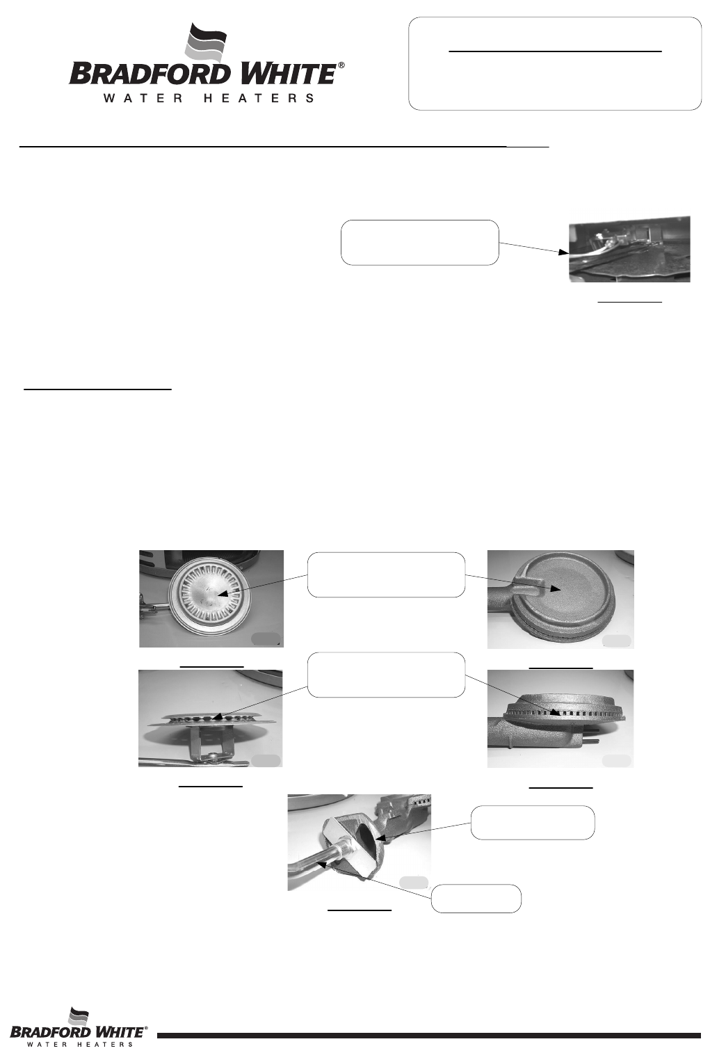
Step 4. On cast iron burners, inspect
for any debris build up inside
burner venturi. If found,
disconnect main burner feedline
from burner and remove debris
build up.
Burner Venturi
Opening
Feedline
Figure 38
21