


10
THERMOCOUPLE REPLACEMENT
Step 1. Turn off gas supply to water heater. Rotate knob of combination
thermostat/gas valve to “OFF” position.
Step 2. Remove outer jacket door.
Step 3. Remove right side of inner door per SERVICE PROCEDURE RG-I, steps 3a through 3c.
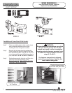
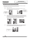
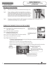
Step 4 Disconnect thermocouple from combination thermostat/gas valve (3/8" wrench). Locate other end of
thermocouple inside of combustion chamber and remove from pilot bracket. Pull firmly pulling away
from the pilot assembly.
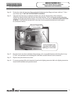
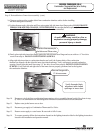
Step 5. Install new thermocouple into pilot bracket making certain the thermocouple is fully engaged into the pilot
bracket. Position thermocouple against left side inner door flange at its original position. Connect other end of
thermocouple to combination thermostat/gas valve (finger tight + ¼ turn).
Step 6. Inspect inner door gasket per
SERVICE PROCEDURE RG-I, Step 4.
Step 7. Install right side inner door per
SERVICE PROCEDURE RG-I,
Step 10 through Step 13
Step 8. To resume operation follow the instructions located on the lighting instruction label or the lighting
instructions located in the installation and operation manual.
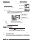
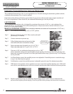
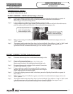
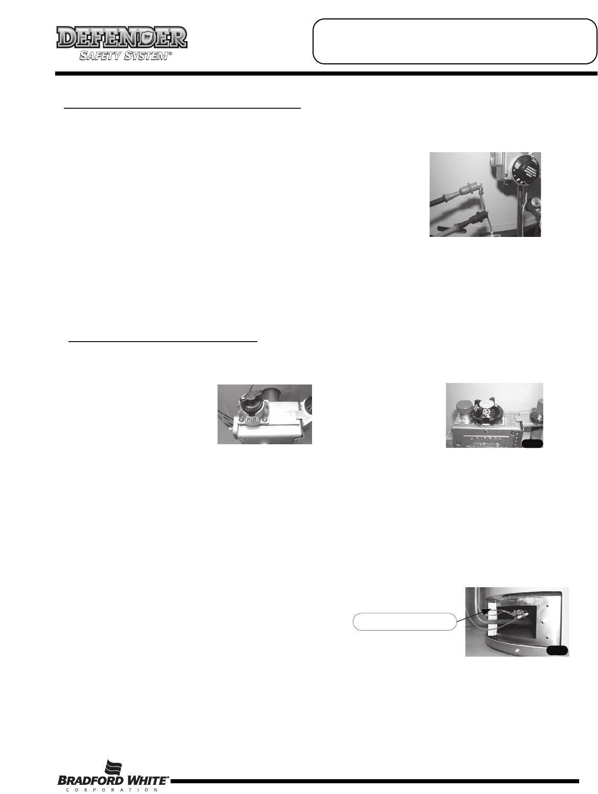
Thermocouple position
For White Rodgers Control,
depress knob slightly and rotate
clockwise to the “OFF” position.
For Robertshaw Control, rotate
knob clockwise to the “OFF”
position.
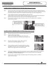
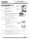
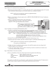
Step 1. Disconnect thermocouple from combination thermostat/gas valve.
Step 2. Using a multimeter capable of measuring millivolts, connect
one alligator clip to the end ball or contact portion of the
thermocouple, and the other alligator clip to copper portion of
the thermocouple.
Step 3. Following the lighting instruction label on the heater, proceed to light the pilot and allow to operate for
three minutes. It will be necessary to hold the pilot button down continuously throughout this test.
A reading of 20 to 30 millivolts indicates good thermocouple output.
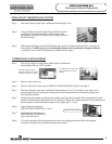
OPEN CIRCUIT THERMOCOUPLE TESTING
SERVICE PROCEDURE RG-II
Thermocouple Testing and Replacement