


8
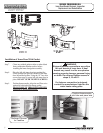
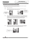
Step 10. Firmly place right side inner door flange against the left side inner door flange and secure with two ¼” drive
screws from step 3c. DO NOT OVER TIGHTEN SCREWS.
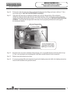
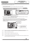
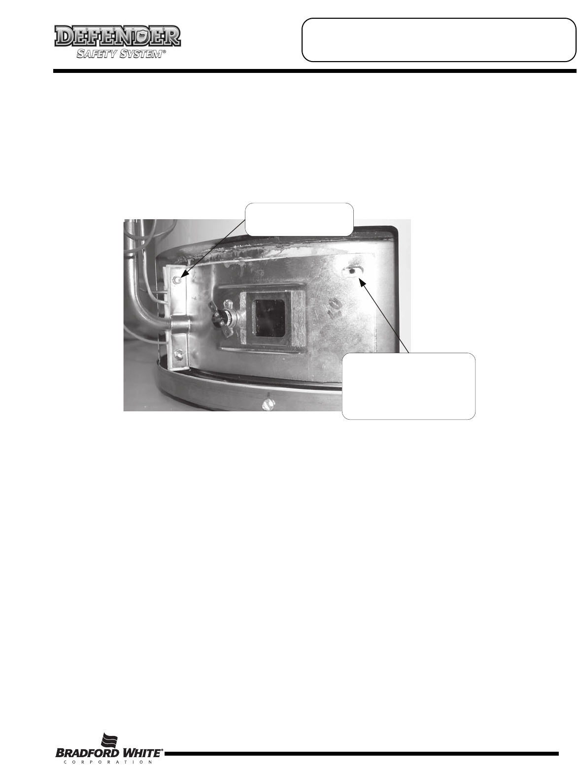
Step 11. Align right side inner door to combustion chamber and verify the fastener holes of the combustion
chamber are aligned with the right side inner door slotted opening. Verify seal integrity around combustion
opening. Secure right side inner door using 1/4” hex drive screws from step 3b. DO NOT OVER TIGHTEN
SCREWS. Verify both left and right sides of the inner door are properly positioned and sealed against
the combustion chamber.
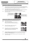
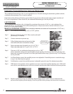
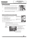
Step 12. Reconnect lead wires from combination thermostat/gas valve to resettable thermal switch (See photo in step
3). Note, wire terminations are interchangeable with either resettable thermal switch connections.
Step 13. Replace outer jacket burner access door.
Step 14. To resume operation follow the instructions located on the lighting instruction label or the lighting instructions
located in the installation and operation manual.
Verify threaded hole
alignment with slotted
openings in inner door.
Secure flange with
¼" drive screws.
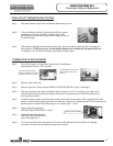
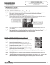
SERVICE PROCEDURE RG-I
Inner Door/Gasket Removal, Inspection
Replacement and Reinstallation