


16
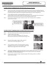
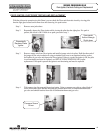
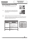
Step 7. Removal of combination thermostat/gas valve.
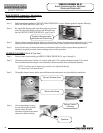
a) Disconnect main burner feedline (¾” wrench), pilot tube (7/16" wrench) and thermocouple (3/8" wrench)
from combination thermostat/gas valve & remove burner from combustion chamber.
NOTE: Feed line nut for natural gas control uses right hand threads,
LP control uses left hand thread.
b) Remove piezo bracket with piezo igniter (refer to SERVICE PROCEDURE RG-IV) from Combination
Thermostat/Gas Valve.
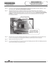
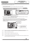
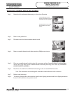
c) Remove Combination Thermostat/Gas Valve from heater,
rotating counter clockwise using a control body wrench or a
length of ½" NPT pipe threaded into inlet of control.
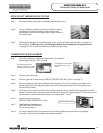
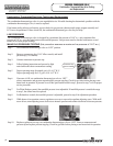
Step 8. Installation of Combination Thermostat/Gas Valve.
a) Install new combination thermostat/gas Valve using a control body wrench or a length of ½" NPT
pipe threaded into inlet of control. DO NOT OVER TIGHTEN. Use caution not to damage cast
aluminum body of combination thermostat/gas valve. Be certain not to damage the bundled wire
leads. Note: Combination thermostat/gas Valve must be installed in proper upright position to
assure the feedline will align properly at the inner door flange.
DO NOT OVER TIGHTEN. If control is turned past proper alignment, do not
reverse direction to align.
b) Reattach Piezo bracket with Piezo igniter to combination thermostat/gas valve.
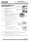
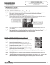
c) Reattach main burner feedline, pilot tube and thermocouple to combination thermostat/gas valve.
NOTE: Feedline nut for natural gas control uses right hand threads,
LP control uses left hand thread.
d) Gather wire leads of combination thermostat/gas valve and Piezo igniter and secure along side of
feedline using new wire tie provided.
e) Connect gas supply piping to inlet of control. Use back up wrench on wrench boss of control, never
use back up wrench on body of control.
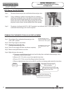
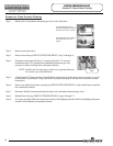
Step 9. Reinstallation of inner door assembly.
a) Prior to reinstallation of inner door, fully inspect inner door gasket for the following:
> Tears > Gasket Adhesion to inner door
> Missing Material > Other imperfections that will inhibit proper seal
> Cracks > Material left on combustion chamber
> Dirt or debris
If the gasket is not effected by any of the above, gasket replacement will not be required. If replacement is
required, replace using new gasket kit following the instructions provided with kit.
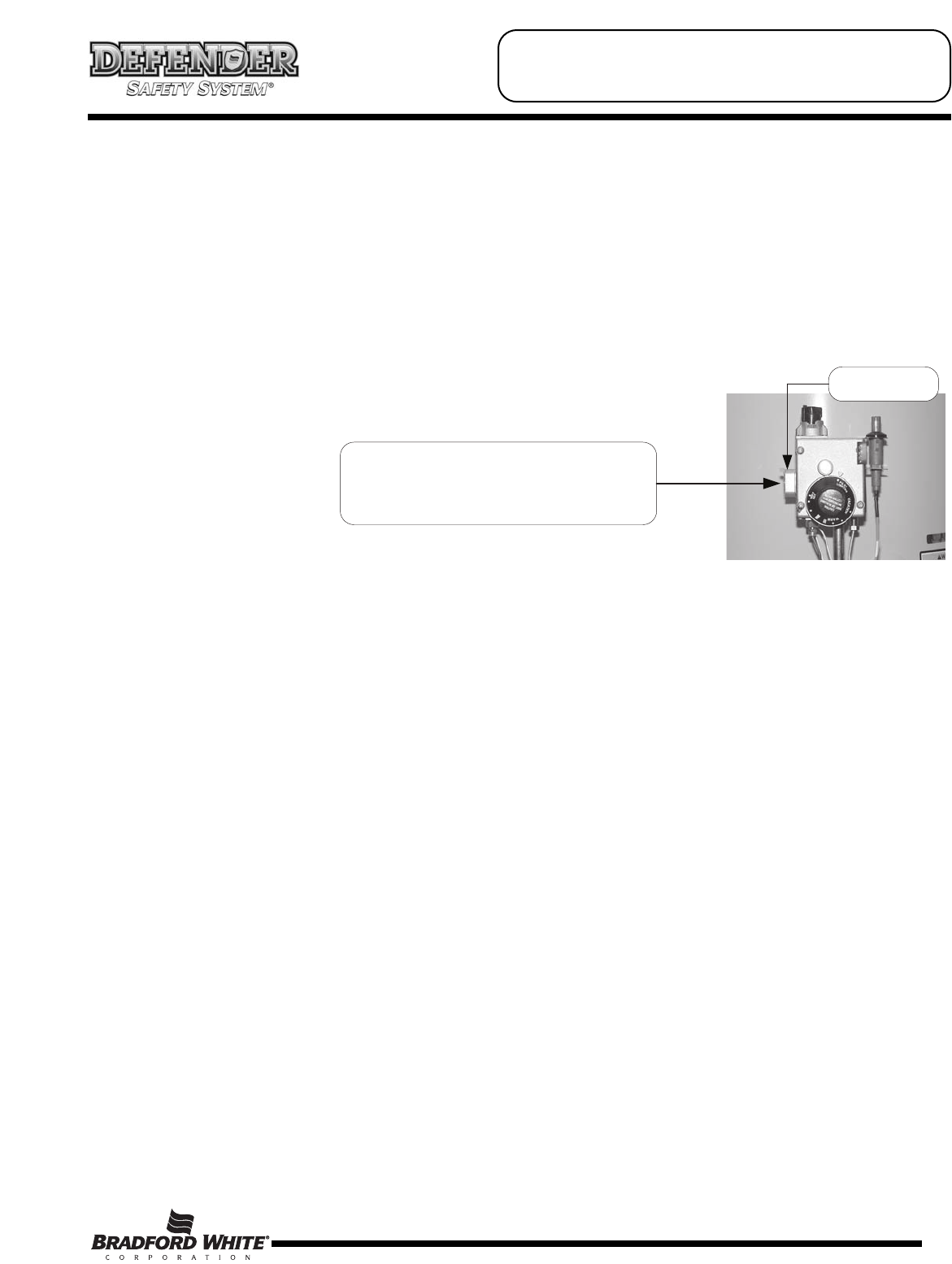
To remove or install control, insert
only ½" NPT threaded pipe into inlet
and use to loosen or tighten control.
Wrench Boss
SERVICE PROCEDURE RG-V
Combination Thermostat/Gas Valve Testing
and Replacement