


9
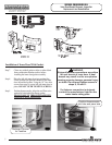
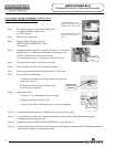
Step 1. Closed circuit testing is the preferred method for testing thermocouple. Following the lighting instruction
label on the heater, proceed to light the pilot and allow to operate for three minuets. If the pilot will not stay
lit, hold the pilot button (located on the combination thermostat/gas valve) down during this test
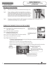
Step 2. Using a multimeter capable of measuring millivolts, connect one lead
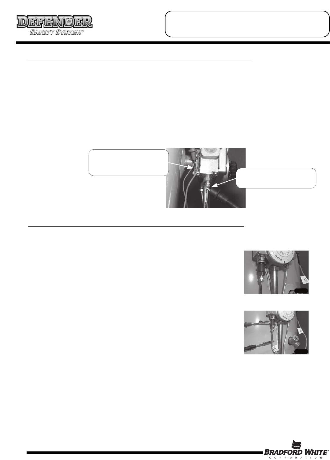
using an alligator clip to the copper sheath of the thermocouple, use the second lead of the multi meter to
probe the top terminal located at the back of the combination thermostat/gas valve.
Step 3. If meter reads 10 millivolts or higher, the thermocouple is OK. If reading is below 10 millivolts,
replace the thermocouple.
CLOSED CIRCUIT THERMOCOUPLE TESTING (White Rodgers Control)
Probe top terminal on
back of combination
thermostat/gas valve
Alligator clip to copper
sheath of thermocouple
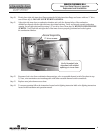
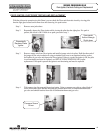
Step 1. Disconnect thermocouple from combination thermostat/gas valve.
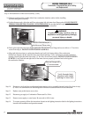
Step 2. Connect a thermocouple adaptor
(BWC P/N 239-44642-00, Robertshaw P/N 75036) at the
thermocouple location in the combination thermostat/gas valve.
Step 3. Reconnect thermocouple to adaptor. Make certain all
connections are tight (finger tight plus ¼ turn)
Step 4 Using a multimeter capable of measuring millivolts, connect
one alligator clip to the set screw of the adaptor, and the other
alligator clip to copper portion of the thermocouple.
Step 5. Following the lighting instruction label on the heater, proceed to light the pilot and allow to operate for
three minuets. If the pilot will not stay lit, hold the red reset button (located on the combination
thermostat/gas valve) down during this test
Step 6. If meter reads 13 millivolts or higher, the thermocouple is OK. If reading is below 13 millivolts
replace the thermocouple.
CLOSED CIRCUIT THERMOCOUPLE TESTING (Robertshaw Control)
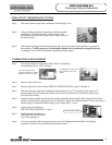
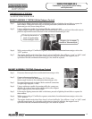
SERVICE PROCEDURE RG-II
Thermocouple Testing and Replacement