


19
Step 3. Fully inspect inner gasket per SERVICE PROCEDURE RG-I, step 4. Replace gasket if required following
SERVICE PROCEDURE I, steps 5 & 6.
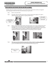
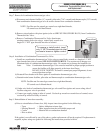
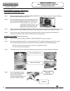
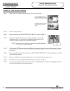
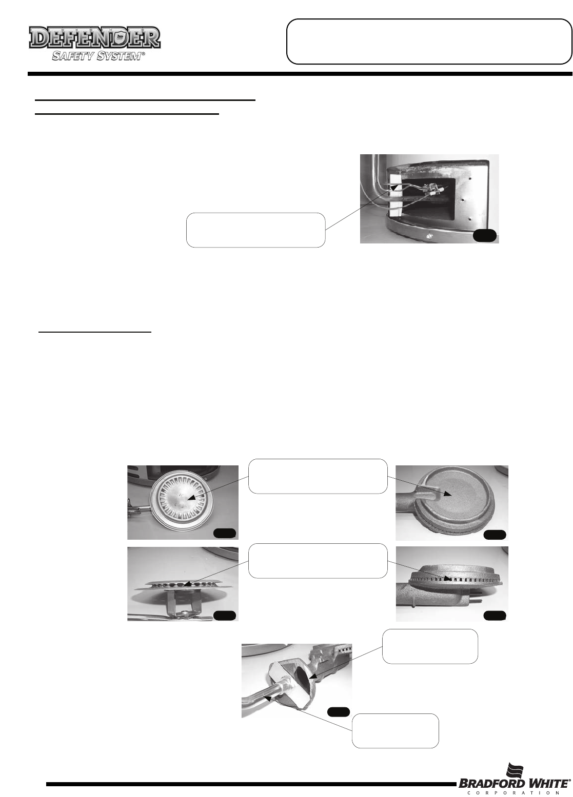
Step 4. Be certain that thermocouple, pilot tube and piezo wire are
routed by inner door flange as shown and Reinstall inner
door per SERVICE PROCEDURE RG-I, step 10 and 11.
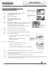
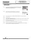
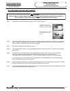
Step 5. Observe burner operation through sight glass of inner door. Burner should operate as adjusted in step 2, if not,
repeat procedure compensating air shutter position for proper burner operation with inner door in place.
Step 6. It may be necessary to clean main burner or main burner orifice to achieve proper burner operation. If
cleaning is required proceed to burner cleaning section in this procedure.
MAIN BURNER: Inspection, Adjustment,
Cleaning and Replacement (cont.)
Position thermocouple,
pilot tube and Piezo wire.
BURNER CLEANING (Steel & Cast Iron)
Step 1. Remove inner door assembly per SERVICE PROCEDURE RG-I, steps 1 through 3c.
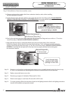
Step 2. Disconnect main burner feed line (¾ wrench), pilot tube (7/16 wrench) and thermocouple (3/8) wrench
from combination thermostat gas valve and remove burner assembly from combustion chamber.
NOTE: Feedline nut for natural gas control uses right hand threads,
LP control uses left hand thread.
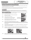
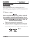
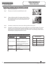
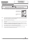
Step 3. Thoroughly inspect burner surface area and burner ports and remove any loose debris accumulation.
Burner Surface Area
Burner Port Area
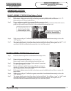
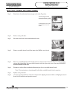
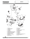
Step 4. On cast iron burners, inspect
for any debris build up inside
burner venturi. If found,
disconnect feedline from burner
and remove debris build up.
Burner Venturi
Opening
Feedline
SERVICE PROCEDURE RG-VI
Burner Operation Inspection, Adjustment
Cleaning and Replacement