


21
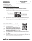
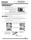
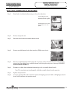
Step 1. Remove outer jacket door.
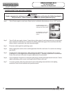
Step 2. Disconnect wire leads from resettable thermal switch.
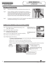
Step 3. Using a multimeter capable of measuring continuity (Ohms),
place one probe of meter on one of the brass connection tabs of
the resettable thermal switch, and the remaining probe on the
other connection tab.
Step 4. If continuity is indicated, the switch is closed, allowing millivolt current to pass.
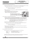
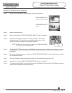
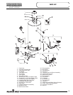
Step 5. If continuity is not indicated, the switch is open, possibly due to an over heating condition. The switch is
designed to open at predetermined temperatures depending on model. An open switch can be reset by
depressing the red colored button located at the center of the switch. The overheating condition must be
determined prior to putting the heater back in service.
RESETTABLE THERMAL SWITCH CONTINUITY TESTING
PROBABLE CAUSE FOR RESETTABLE THERMAL SWITCH ACTIVATION
PROBABLE CAUSE CORRECTIVE ACTION
Insufficient combustion Air
1. Verify adequate combustion air supply is
available.
2. Clear jacket slot openings of any dirt, dust,
restrictions or other obstructions.
3. inspect flame arrestor plate and clean with
stiff brush and/or vacuum to remove scale
deposits and debris.
1. Weak switch or switch
out of calibration.
2. Incorrect switch.
1. Replace resettable thermal switch
2. Verify switch color code and approximate
temperature.
Flammable vapor incident 1. Replace water heater.
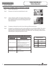
Color Code
Blue
Approximate switch
activation temperature
(open)
240°
Yellow 270°
Red 290°
Resettable thermal switch
color code reference.
SERVICE PROCEDURE RG-VII
Resetting Thermal Switch
Testing and Replacement