


15
COMBINATION THERMOSTAT/GAS VALVE REPLACEMENT
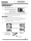
Step 1. Rotate knob of the combination thermostat/gas valve
to the “OFF” position.
Step 2. Turn off gas supply to water heater.
Step 3. Disconnect gas supply line from
combination thermostat/gas valve.
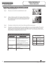
Step 4. Turn off water supply and drain water heater completely.
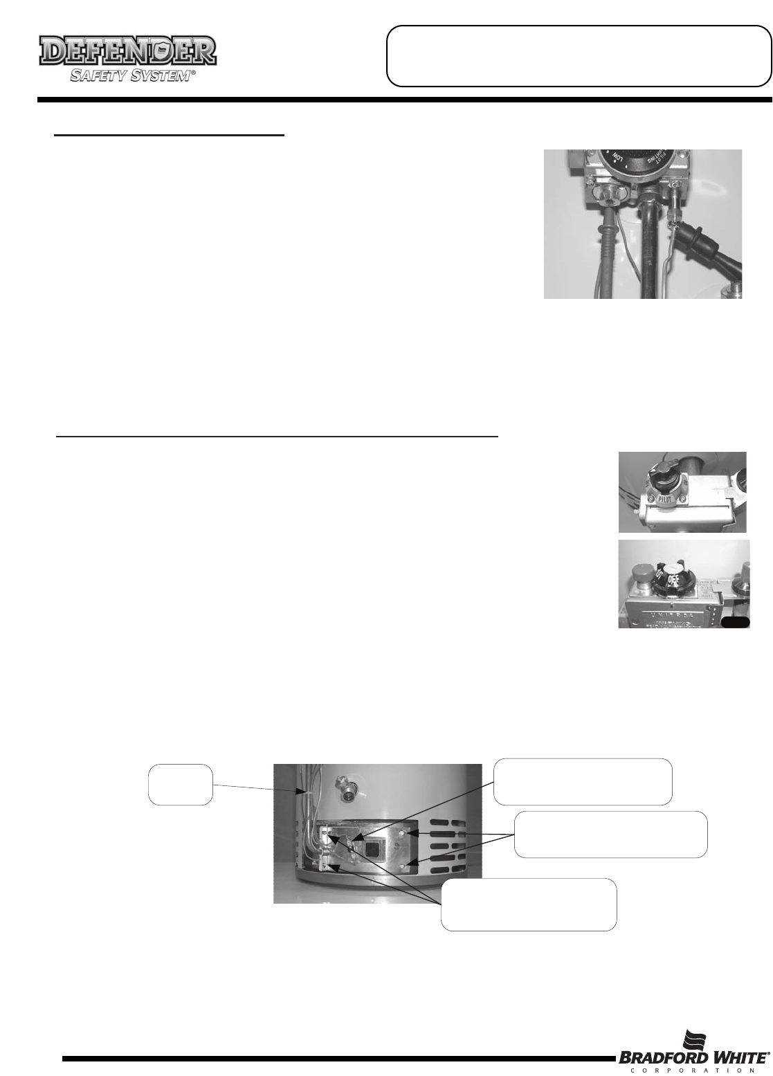
Step 5. Remove outer jacket burner access door.
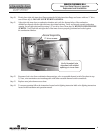
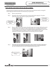
Step 6. Right side inner door removal.
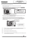
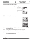
a) Disconnect resettable thermal switch wire leads (leading from combination thermostat/gas valve)
and remove wire tie from feedline.
b) Remove (2) 1/4" hex drive screws from right side inner door.
c) Remove (2) 1/4" drive screws from flange section of inner door.
d) Remove right side inner door and set aside. Be careful not to damage gasket material on inner door.
Resettable Thermal Switch
Wire Connection
¼" Hex Drive Screws shown on
Right Side Inner Door.
¼" Hex Drive Screws at
Flange section of Inner Door
Remove
Wire Tie
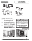
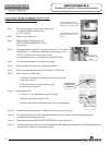
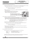
For White Rodgers Control,
depress knob slightly and rotate
clockwise to the “OFF” position.
For Robertshaw Control, rotate
knob clockwise to the “OFF”
position.
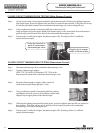
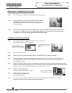
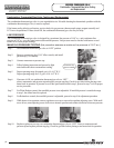
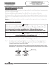
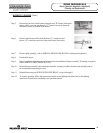
Step 1. Disconnect thermocouple from combination thermostat/gas valve.
Step 2. Using a multimeter capable of measuring Ohms (or continuity),
attach one lead (alligator clip) to the pilot tube. Insert the other lead
(probe) fully into the magnet opening, Be sure the probe makes
contact only at the top center of the magnet opening. Do not allow
the probe to make contact with the threaded sides of the opening.
Step 3. If continuity is indicated, the ECO is OK. If continuity is not indicated, the ECO has opened and the
combination thermostat/gas valve must be replaced.
ECO (Energy Cut Off) TESTING
SERVICE PROCEDURE RG-V
Combination Thermostat/Gas Valve Testing
and Replacement