


17
Step 9. Reinstallation of inner door assembly. (cont.)
b) Clean any gasket residue or other debris from combustion chamber surface before installing
the inner door/gasket assembly.
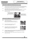
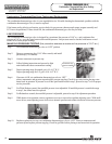
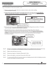
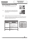
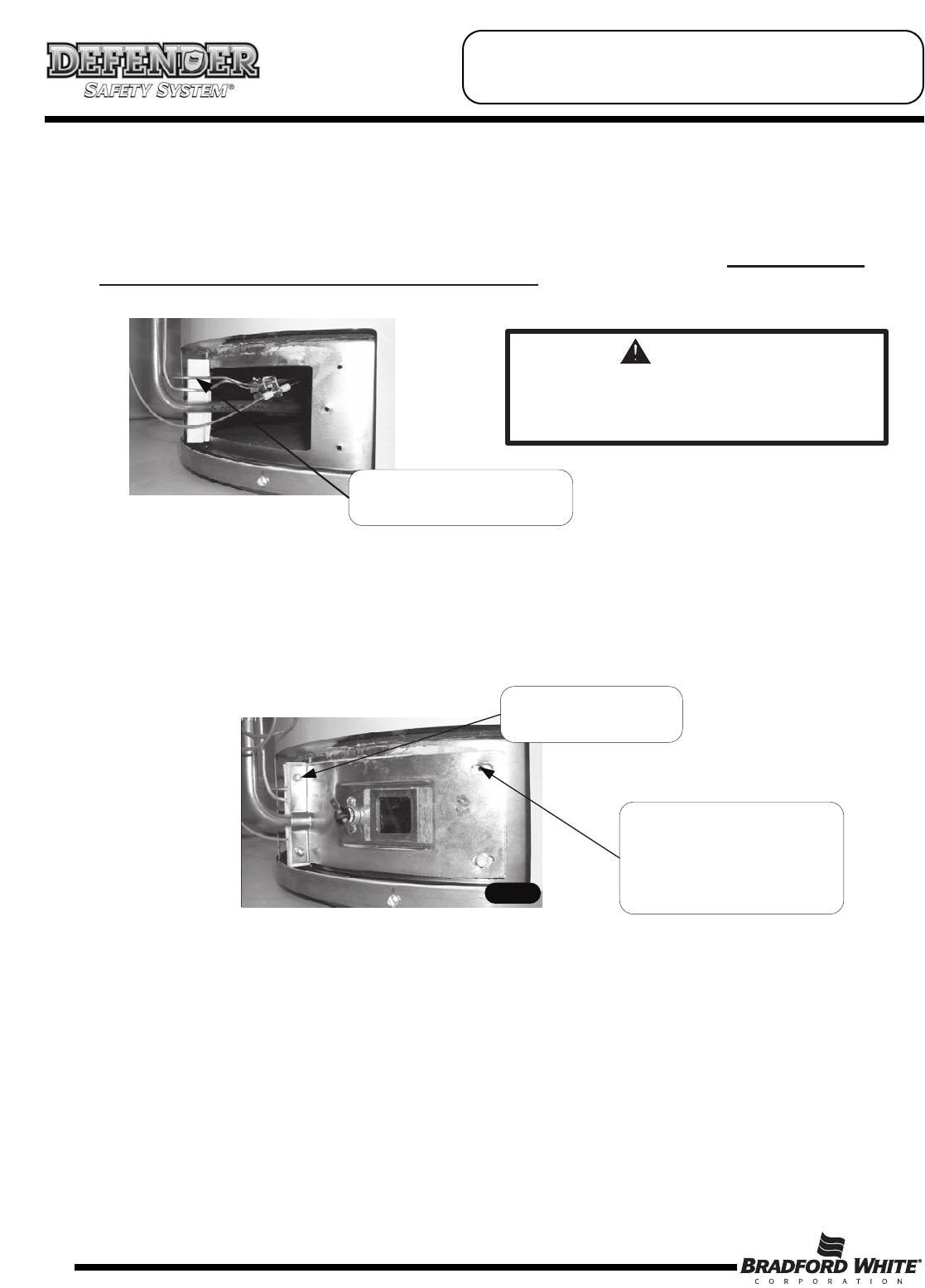
c) Position thermocouple, pilot tube and Piezo wire against left side inner door flange gasket. DO NOT ROUTE
THROUGH RADIUSED CHANNEL WITH FEEDLINE. Be sure that thermocouple and pilot tube are not
in position to interfere with outer jacket burner access door when reinstalled.
Position thermocouple,
pilot tube and Piezo wire.
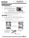
WARNING
A seal breach may result in a fire or
explosion causing property damage,
personal injury or death.
d) Firmly place right side inner door flange against the left side inner door flange and secure with two ¼” hex drive
screws from step 6c. DO NOT OVER TIGHTEN SCREWS.
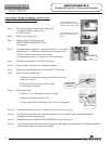
e) Align right side inner door to combustion chamber and verify the fastener holes of the combustion
chamber are aligned with the right side inner door slotted openings. Verify seal integrity around combustion
opening. Secure right side inner door using 1/4” hex drive screws from step 6b. DO NOT OVER TIGHTEN
SCREWS. Verify both left and right sides of the inner door are properly positioned and sealed against
the combustion chamber.
Step 10. Reconnect wire leads from combination thermostat/gas valve to resettable thermal switch (See photo in step
6). Note: wire terminations are interchangeable with either resettable thermal switch connection.
Step 11. Replace outer jacket burner access door.
Step 12. Reconnect gas supply to Combination Thermostat/Gas Valve.
Step 13. Resume water supply to water heater. Be sure tank is full of water.
Step 14. To resume operation follow the instructions located on the lighting instruction label or the lighting instructions
located in the installation and operation manual.
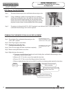
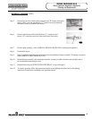
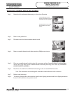
Verify threaded hole
alignment with slotted
openings in inner door.
Secure flange with
¼" drive screws.
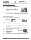
SERVICE PROCEDURE RG-V
Combination Thermostat/Gas Valve Testing
and Replacement