


ICP-CC488 | Installation Guide | 21.0 Optional Equipment EN | 90
Bosch Security Systems, Inc. | 12/08 | F01U089457-02
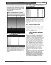
Then, find the RF device number in Section 20.3 (for
devices 1 through 8) on page 89 or Section 20.4 (for
devices 9 through 16) on page 89. Use the device’s
corresponding location (616 through 631). To map
the selected device to a zone other than the default
zone, refer to Table 62 and use the correct
hexadecimal value.
Table 62: Hexadecimal Values for Zone Nos.
Zone Number Hexadecimal Value
1 00
2 01
3 02
4 03
5 04
6 05
7 06
8 07
9 08
10 09
11 10
12 11
13 12
14 13
15 14
16 15
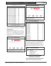
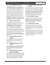
20.6 RF Device Signal Strength (Devices
1 to 8) (Read Only)
Location
801 to 808
Location Default
RF Device 1 801 0
RF Device 2 802 0
RF Device 3 803 0
RF Device 4 804 0
RF Device 5 805 0
RF Device 6 806 0
RF Device 7 807 0
RF Device 8 808 0
0-15 Mapping RF Device to Zone 1-16
These locations allow you to view the received signal
strength for RF wireless Devices 1 to 8. Location 801
displays the signal strength of Device 1, Location 802
displays the signal strength of Device 2, and so on.
The signal strength is measured from 0 (lowest) to 8
(highest).
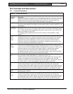
20.7 RF Device Signal Strength (Devices
9 to 16) (Read Only)
Location
809 to 816
Location Default
RF Device 9 809 0
RF Device 10 810 0
RF Device 11 811 0
RF Device 12 812 0
RF Device 13 813 0
RF Device 14 814 0
RF Device 15 815 0
RF Device 16 816 0
These locations allow you to view the received signal
strength for RF wireless Devices 9 to 16. Location
809 displays the signal strength of Device 9, Location
810 displays the signal strength of Device 10, and so
on. The signal strength is measured from 0 (lowest) to
8 (highest).
21.0 Optional Equipment
Bosch Security Systems, Inc. manufactures a number
of accessories that can be used in conjunction with
the ICP-CC488 Control Panel. These optional pieces
of equipment enhance certain features to make the
system extremely flexible.
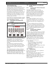
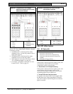
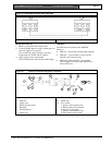
21.1 RE012/RE013 2 Channel/4
Channel Hand Held Transmitters
304 MHz
These hand-held radio transmitters can be used in
conjunction with the RE005 304 MHz RF Receiver
to operate the system remotely. Both hand-held
transmitters can remotely arm and disarm the system
in AWAY Mode or STAY Mode 1 and can activate
remote Panic Alarms. The 4-channel hand-held
transmitter can also operate outputs such as garage
doors, swimming pool pumps, or outside lights.
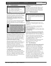
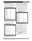
21.2 RE005 2 Channel Radio Interface
The 2-channel radio interface allows customers to
operate control panels remotely and to control two
on-board relays. The interface can be used as a stand-
alone receiver, independent of an ICP-CC488
Control Panel, used solely for remote control of
external devices connected to the two on-board
relays.
The interface’s operating frequency is 304 MHz with
the ability to store up to 120 radio remote codes.
Connect the interface to an ICP-CC488 Control
Panel using a three-wire connection in parallel with
the codepad and select Option 8 in Location 495
(refer to Section 18.4 System Options 4 on page 82).