


ICP-CC488 | Installation Guide | 20.0 RF Information EN | 89
Bosch Security Systems, Inc. | 12/08 | F01U089457-02
8 – Enable RF Jamming Monitor
If this option is selected, the RF receiver monitors the
background RF levels. If this level reaches a preset
limit, the receiver assumes it is being jammed. This
generates a fault on the codepad and sends an RF
Jamming Report to the monitoring station.
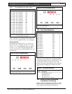
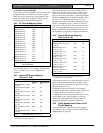
20.2 RF Device Mapping Option
Location
600 to 615
Location Default
Map RF Device 1 600 1
Map RF Device 2 601 1
Map RF Device 3 602 1
Map RF Device 4 603 1
Map RF Device 5 604 1
Map RF Device 6 605 1
Map RF Device 7 606 1
Map RF Device 8 607 1
Map RF Device 9 608 1
Map RF Device 10 609 1
Map RF Device 11 610 1
Map RF Device 12 611 1
Map RF Device 13 612 1
Map RF Device 14 613 1
Map RF Device 15 614 1
Map RF Device 16 615 1
0
1
Mapping Disabled
Mapping Enabled
These locations allow you to enable or disable any of
the sixteen RF devices. For example, if location 607
is set to “0”, RF device 7 is not mapped and is
disabled.
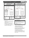
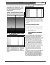
20.3 Default RF Device Mapping
(Devices 1 to 8)
Location
616 to 623
Location Default Value*
Map RF Device 1 to Zone
(1 to 16)
616 00
Map RF Device 2 to Zone
(1 to 16)
617 01
Map RF Device 3 to Zone
(1 to 16)
618 02
Map RF Device 4 to Zone
(1 to 16)
619 03
Map RF Device 5 to Zone
(1 to 16)
620 04
Map RF Device 6 to Zone
(1 to 16)
621 05
Map RF Device 7 to Zone
(1 to 16)
622 06
Map RF Device 8 to Zone
(1 to 16)
623 07
0-15 Mapping RF device to zone 1-16
* The programming for zone numbers 1 through 8 is in
hexadecimal code (00 through 15).
These locations allow you to allocate RF wireless
devices 1 to 8 to any of the 16 zones on the control
panel. You cannot map more than one RF wireless
device to the same zone. Refer to Section 20.4 Default
RF Device Mapping (Devices 9 to 16) to map RF wireless
devices 9 to 16. By default, RF devices 1 to 8 are
mapped separately to each of the eight zones (that is,
Device 1 is mapped to Zone 1, Device 2 to Zone 2,
and so on). Locations 616 to 623 and locations 624 to
631 can be programmed as any value from 00 to 15.
Refer to Section 20.5 Using Hexadecimal Values for RF
Device Mapping on page 89 for mapping information.
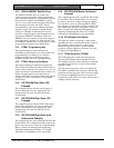
20.4 Default RF Device Mapping
(Devices 9 to 16)
Location
624 to 631
Location Default
Map RF Device 9 to Zone
(1 to 16)
624 08
Map RF Device 10 to
Zone (1 to 16)
625 09
Map RF Device 11 to
Zone (1 to 16)
626 10
Map RF Device 12 to
Zone (1 to 16)
627 11
Map RF Device 13 to
Zone (1 to 16)
628 12
Map RF Device 14 to
Zone (1 to 16)
629 13
Map RF Device 15 to
Zone (1 to 16)
630 14
Map RF Device 16 to
Zone (1 to 16)
631 15
0-15 Mapping RF device to zone 1-16
* The programming for zone numbers 9 through 16 is in
hexadecimal code (00 through 15).
These locations allow you to map RF wireless control
panel. You cannot map more than one RF wireless
device to the same zone. Refer to Section 20.3 to map
RF wireless devices 1 to 8.
By default, RF devices 9 through 16 are mapped
separately to each of the eight zones (that is, Device 9
is mapped to Zone 9, Device 10 to Zone 10).
Locations 616 to 623 and locations 624 to 631 can be
programmed as any value from 00 to 15. Refer to
Section 20.5 Using Hexadecimal Values for RF Device
Mapping on page 89 for mapping information.
20.5 Using Hexadecimal Values for RF
Device Mapping
To map an RF device, first select a device number
and enable the device. Refer to Section 20.2 RF Device
Mapping Option on page 89.