


ICP-CC488 | Installation Guide | 11.0 Dialer Information EN | 48
Bosch Security Systems, Inc. | 12/08 | F01U089457-02
10.2 Basic Pager Display Information
The Pager format supports only eight
zones.
Subscriber ID Number
This is the identification number of the control panel
and is programmed in Locations 034 to 039 for
Receiver 1 and Locations 074 to 079 for Receiver 2
(refer to Section 11.5 Subscriber ID Number for Receiver 1
and Receiver 2 on page 50). The pocket pager displays
only the last three digits of the Subscriber ID
Number.
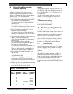
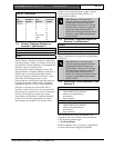
Zone Status
The zone status display shows you the status of each
zone (1 to 8) of the control panel. Table 44 on page
48 describes each status number when displayed on a
pocket pager.
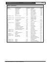
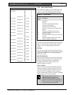
Table 44: Zone Status Display
Status Zone Description
0
Zone normal
The zone is sealed.
1
Alarm
The zone is unsealed and in alarm.
2
Zone bypassed
A system operator manually isolated the
zone. Refer to Section 3.11 Isolating
Zones on page 17for information about
manually isolating a zone(s) before arming
the system. Refer to Section 15.3 Zone
Status – Bypass Reports on page 65 for
more information.
3 Zone trouble
A zone was left unsealed after the end of
Exit Time. Refer to Section 15.4 Zone
Status – Trouble Reports on page 65for
more information.
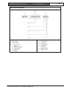
System Status
The system status information shown by four digits is
defined in Figure 9 on page 47.
• The first digit indicates whether the system is
armed or disarmed.
• The sec digit indicates if a codepad alarm was
activated by the operator (refer to Section 3.7
Codepad Duress Alarm through Section 3.10
Codepad Medical Alarm on page 17 for more
information).
• The third digit indicates the status of the AC
MAINS supply.
• The fourth digit indicates whether a system fault
occurred at the control panel (refer Section 3.12
Fault Analysis Mode on page 18 for more
information.
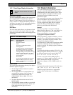
11.0 Dialer Information
This section outlines the programming information
required for the ICP-CC488 Control Panel when
communicating with a base station receiver. These
parameters specify the telephone numbers to call,
transmission formats, handshake tones, and
transmission speeds.
The control panel can report event information from
two on-board dialers. The first dialer reports to
Receiver 1 and the sec dialer reports to Receiver 2.
You can program each dialer with two separate
telephone numbers, handshake tone, reporting
format type, and Subscriber ID Number.
Example
You can set up Dialer 1 to report in Domestic
Dialing Format to Receiver 1 and set up Dialer 2 to
report to a base station receiver in Contact ID
Format only if Dialer 1 is unsuccessful.
To program a telephone number:
When programming a telephone number, you must
program a 0 as a 10. Each location in the primary,
secondary, and callback telephone numbers stores
one digit of the telephone number.
You must insert a 0 at the end of a telephone number
to indicate to the dialer the end of the telephone
number is reached. The dialing sequence terminates
when a 0 appears.
Example
To program the telephone number 9672 1055 as the
Primary Telephone Number for Receiver 1, program
the following sequence into Locations 000 to 015:
[9 6 7 2 1 10 5 5 0 0 0 0 0 0 0 0]
To enter a 4-sec pause in the dialing sequence,
program a 13. A pause might be necessary when the
dialer communicates through an old (slower)
telephone exchange or when a PABX system is in
place.
Example
To program the number 02 pause 9 672 1055, enter:
[10 2 13 9 6 7 2 1 10 5 5 0 0 0 0 0].
Table 45 on page 55 shows how to program the
numbers, keys, and functions for a telephone
number.