


9
CF500/CF800 Burner Manual
Mount fl ange(s) on air tube
This section does not apply to burners with welded
fl anges.
Do not install air tube on burner.
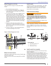
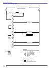
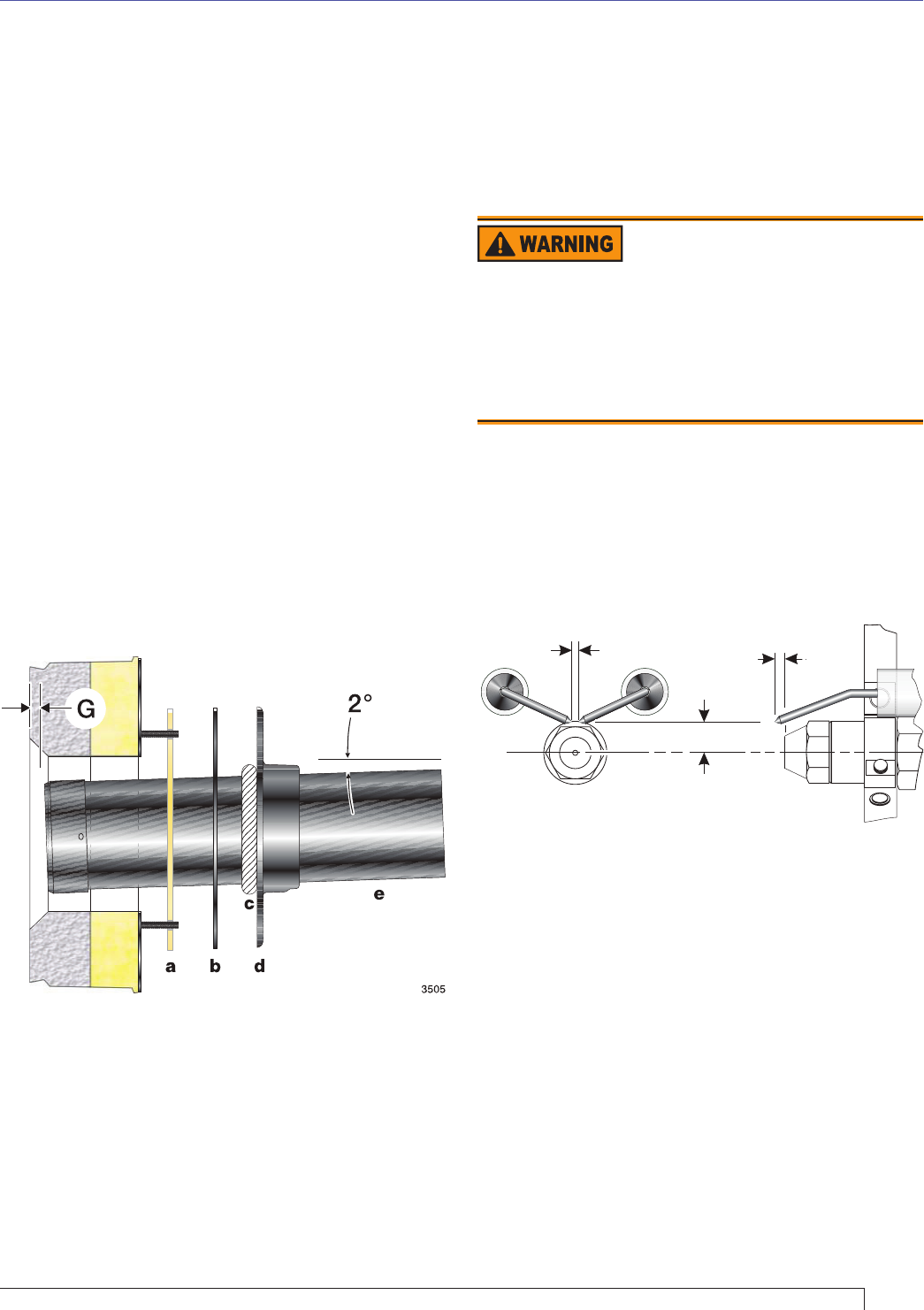
For non-pressure fi ring fl ange, refer to Figure 4:
Install gasket (item a) and fl ange (item d). Ignore
the next paragraph.
For pressure-fi ring fl ange, refer to Figure 4: Slide
gasket (item a) onto the air tube, making sure
the top of the air tube is up. Pre-drill holes in the
pressure fi ring plate (item b) to match the appliance
studs. Slide the pressure fi ring plate (item b) and
fl ange (item d) onto the air tube as shown. Wrap
ceramic fi ber rope (item c) around the air tube and
press tightly into the inside diameter of the fl ange
(item d).
Slide the air tube (item e) into position in the
appliance front. Tighten the fl ange-mounting-stud
nuts. Set the insertion of the air tube so dimension
G is 1/4” nominal.
Pitch the air tube at 2° from horizontal as shown
and secure the fl ange to the air tube.
1.
2.
3.
4.
5.
Figure 4 - Mount fl ange(s) on air tube
Section: Mount the Burner
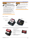
Mount air tube to burner
Insert the air tube into the burner housing. Carefully align
the the four screw holes.
Attach the air tube to the burner using the four provided
screws.
Install nozzle line assembly
Insert the nozzle line assembly into the burner air tube.
Reference Figure 6.
Slide the secondary adjusting plate (Figure 7, item f)
completely to the left on the indicator adjusting plate (item
e). Finger tighten acorn nut (item c) to secure the two
plates together. Slide both plates completely to the right
(Indicator Plate will read 0). Tighten fastener (item d).
Install the spline nut on the end of the nozzle line, leaving
the nut loosely placed so the plates can be moved.
50001
End view Side view
3/16” - 7/32”
gap
1/4” in front
of nozzle
3/16” above
nozzle center
R
P
Q
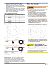
Figure 5 - Nozzle and nozzle line assembly
Legend (Figure 5)
P
Nozzle centerline to electrode tip = 3/16”
Q
Nozzle face to electrode tip = 1/4”
R
Electrode spacing = 3/16” gap
Maintain Electrode
Specifi cations
Failure to properly maintain these specifi cations
could cause ignition malfunction, puff-back of hot
gases, heavy smoke, asphyxiation, explosion and
fi re hazards.
Adjust the electrode gap and position in relation to the
nozzle to the following specifi cations.
Install nozzle
Install the oil nozzle in the nozzle adapter. Use a 3/4”
open-end wrench to steady the nozzle adapter and
a 5/8” open-end wrench to turn the nozzle. Tighten
securely but do not over-tighten.
Check electrode settings
Check, and adjust if necessary, the critical dimensions
shown in Figure 5. Verify that the oil tube assembly
and electrodes are in good condition, with no cracks or
damage.