


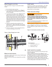

20
Cad Cell Resistance Measurement
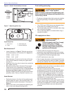
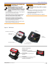
If the Beckett 7505 control is equipped with the
GeniSys Display Module, part 52067U, the cad cell
resistance can be selected and read on the LCD
screen. Also, the GeniSys Contractor Tool, part
52082U, can be used for this purpose.
If these are not available, the cad cell leads can
be unplugged from the control and the resistance
measured with a meter in the conventional way.
Conduct these tests with fl ame present.
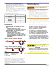
Flame Detection Range
Normal = 0 to 1600 ohms
Limited = 1600 ohms to lockout
Resetting From Restricted or Hard Lockout
If the control continues to lockout without a satisfi ed
call for heat, or fails the motor relay check, the
control enters Hard (restricted) Lockout in order to
limit accumulation of unburned oil in the combustion
chamber
To reset 7505, hold the button down for 15 seconds
until the red light turns off and the yellow light turns
on.
To reset R7184 control hold reset button down for 30
seconds until the LED fl ashes once for one second.
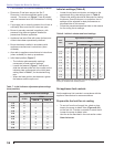
Set combustion using instruments
Allow the burner to run for approximately 5 to 10
minutes.
Set the stack or over-fi re draft to the level specifi ed
by the appliance manufacturer.
Natural Draft Applications; typically over-fi re
draft is -0.01” or -0.02” w.c.
Direct Venting; typically may not require draft
adjustment.
High Effi ciency/Positive Pressure Appliances;
also vary from traditional appliances (see
manufacturer’s recommendations).
Follow these four steps to properly adjust the
burner:
Step 1: Adjust the air shutter/band until a trace
of smoke is achieved.
Step 2: At the trace of smoke level, measure the
CO
2
(or O
2
) . This is the vital reference point for
further adjustments. Example: 13.5% CO
2
(2.6%
O
2
)
○
○
○
○
○
1.
2.
○
○
○
3.
Step 3: Increase the air to reduce the CO
2
by
1.5 to 2 percentage points. (O
2
will be increased
by approximately 2.0 to 2.7 percentage points.)
Example: Reduce CO
2
from 13.5% to 11.5%
(2.6% to 5.3% O
2
).
Step 4: Recheck smoke level. It should be Zero.
This procedure provides a margin of reserve air
to accommodate variable conditions.
If the draft level has changed, recheck the smoke
and CO
2
(or O
2
) levels and readjust the burner, if
necessary
Once combustion is set, tighten all fasteners on air
band, air shutter and escutcheon plate.
Start and stop the burner several times to ensure
satisfactory operation. Test the primary control
and all other appliance safety controls to verify
that they function according to the manufacturer’s
specifi cations.
Check the breech draft pressure against the
appliance manufacturer’s recommended setting
(typically + 0.1” W.C.). If the breech pressure is
higher or lower than recommended level, adjust the
appliance breech damper to achieve the specifi ed
setting. Recheck the smoke and CO
2
(or O
2
) levels.
Adjust burner air if necessary.
4.
5.
6.
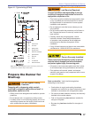
Section: Start the Burner