


8
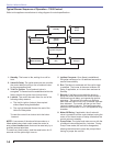
Firebox
pressure
(in w.c.)
CF500 CF800 CF500 CF800
Tube
KK
Tube
KH
Tube
KJ
Tube
KK
Tube
KH
Tube
KJ
No reserve air 10% Turndown
0.0” 5.50 7.00 8.00 4.95 6.30 7.20
0.1” 4.75 6.25 7.50 4.27 5.62 6.75
0.2” 4.00 5.50 6.75 3.60 4.95 6.07
0.3” 3.50 4.50 6.25 3.15 4.00 5.62
0.4” 2.75 3.75 5.50 2.47 3.37 4.95
0.5” 2.00 3.00 5.00 1.80 2.70 4.50
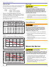
Note: The above ratings may vary 5% due to variations in actual job
conditions.
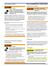
Table 2 - Air tube capacities vs fi rebox pressure
Section: Mount the Burner
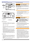
Stray Light
Dust and Moisture
Protect Against Stray Light
Lockout
Failure to follow these instructions could cause
loss of burner operation resulting in no heat, an
unplanned process interruption, work stoppage
and the potential for frozen plumbing or other cold
weather property damage.
The control must detect a dark, no-fl ame condition in
order to start the burner or it will hold in the stray light
lockout mode.
Shield the burner from direct exposure to intense light.
y
y
Protect Against Dust and
Moisture
Wet, dusty environments could lead to blocked
air passages, corrosion damage to components,
impaired combustion performance and result in
asphyxiation, explosion or fi re.
This burner is designed for clean, dry installations.
Electrical controls are not protected against rain or
sprayed water.
Keep the installation clear of dust, dirt, corrosive
vapors, and moisture.
Protective covers and more frequent maintenance
may be required.
y
y
y
y
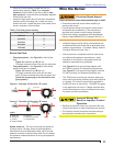
Mount the Burner
Protect the Air Tube From
Overheating
Overheating could cause damage to the air tube and
other combustion components leading to equipment
malfunction and impaired combustion performance.
The end of the air tube must not extend into the
combustion chamber unprotected unless it has
been factory-tested and specifi ed by the appliance
manufacturer.
Position the end of the air tube ¼” back from fl ush
with the refractory inside entry wall to prevent
damage from overheating.
y
y
Verify air tube
The information in this section may be disregarded if the
air tube is supplied by the appliance manufacturer.
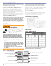
Two tube arrangements are available –
CF500 1.75 to 5.50 GPH
CF800 Tube A — 3.00 to 7.00 GPH
Tube B — 5.00 to 8.00 GPH
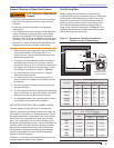
Maximum fi ring capacity depends on the fi rebox
pressure. Use Table 2 to verify the correct air tube type
for the fi ring rate required. Use Tube B only when Tube
A cannot provide the fi ring rate required.
See Figure 2 to verify the correct air tube length and air
tube combination code.
○
○
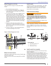
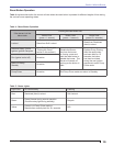
Figure 3a - Firebox Pressure: CF500 with no Reserve Air
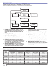
Figure 3b - Firebox Pressure: CF800 with no Reserve Air
0.1 0.2 0.3 0.4 0.5
0.0
5
4
3
2
Firebox Pressure in Inches Water Column (W.C.)
Maximum Firing Rate U.S. GPH
KK
6
0.1 0.2 0.3 0.4 0.5
0.0
6
5
4
3
Firebox Pressure in Inches Water Column (W.C.)
Maximum Firing Rate U.S. GPH
KJ
KH
7
8
9