


6
the fuel unit (oil pump) on the burner. Refer to fuel unit
literature in the literature envelope in the burner carton to
verify allowable suction pressure.
If fuel supply is level with or higher than fuel unit —
When the fuel unit is not required to lift the oil, the
installation is usually suitable for either a one-pipe or
two-pipe oil system. The oil pressure at the inlet of the
fuel unit must not exceed 3 psig.
Refer to the Mount the Burner Section of this manual for
one-pipe or two-pipe fuel supply installation instructions.
If fuel supply is below the fuel unit —
Use a two-pipe oil system when the fuel unit must lift the
oil more than 8 feet if burner is equipped with a B fuel
unit. The return line provided by the two-pipe system is
needed to purge the air from the fuel lines and minimize
the likelihood of air-related problems during operation.
Nozzle Pressure
The fuel unit nozzle port pressure is factory set at 140
psig. Some original equipment manufacturer burner
applications may call for a lower pressure to obtain a
required fi ring rate. Do not change this pressure unless
directed to do so by the appliance manufacturer.
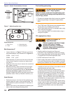
Electrical Supply
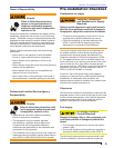
Verify that the power connections available are correct
for the burner. Refer to Figure 1. All power must be
supplied through fused disconnect switches.
Verify Burner Components
Burner, Model CF500 or CF800
Air tube assembly
Mounting fl ange kit
Oil nozzle, per Table 1
— Only 45° to 70° solid pattern
nozzles are recommended unless otherwise specifi ed
by appliance manufacturer. (See specifi c appliance
recommendation sheet or refer to OEM Spec Guide).
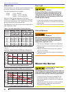
Find the required fi ring rate in the 140 psig column
(factory-set fuel unit pressure). Select the corresponding
nozzle from column 1 (Rated gph @ 100 psig).
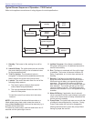
Vent System
○
○
○
○
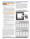
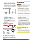
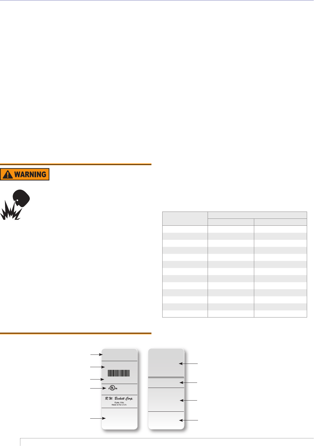
Figure 1. Typical Nameplate
Correct Nozzle and Flow
Rate Required
Incorrect nozzles and fl ow rates could
result in impaired combustion, under-
fi ring, over-fi ring, sooting, puff-back of
hot gases, smoke and potential fi re or
asphyxiation hazards.
Use only nozzles having the brand, fl ow rate (gph),
spray angle and pattern specifi ed by the appliance
manufacturer. Follow the appliance manufacturer’s
specifi cations for the required pump outlet pressure for
the nozzle, since this affects the fl ow rate.
Nozzle manufacturers calibrate nozzle fl ow rates at
100 psig.
This burner utilizes pressures higher than 100 psig,
so the actual nozzle fl ow rate will be greater than the
gph stamped on the nozzle body. (Example: A 2.00
gph nozzle at 140 psig = 2.37 gph.
For typical nozzle fl ow rates at various pressures
see Table 1.
y
y
y
Section: Pre-installation Checklist
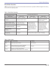
Table 1 - Nozzle Capacities
Rated gph @ 100
psig
Pressure - Pounds per square inch
140 150
1.75 2.07 2.14
2.00 2.37 2.45
2.25 2.66 2.74
2.50 2.96 3.06
2.75 3.24 3.37
3.00 3.55 3.68
3.50 4.13 4.29
4.00 4.70 4.90
4.50 5.30 5.51
5.00 5.90 6.13
5.50 6.50 6.74
6.00 7.10 7.33
6.50 7.65 7.96
The fl ue gas venting system must be in good condition
and must comply with all applicable codes.
LISTED
(FUEL) BURNER
SERIAL NUMBER
050214-00000
Control Circ: 120V/60Hz 4.5A
Motor Circ: 120V/60Hz 4.0A
Model “XX”
Series (Fuel) Burner
For use with Group 8 . . .
MP 1192 XX000 R00
X
X
X
X
X
X
XX000 R00
050214-00000
MFR’S SETTINGS
R.W. Beckett Construction & Setting Data
R.W. Beckett Specifi cation
Number and Revision
Boiler Manufacturer and
Model, When Applicable
Additional Codes
General Model Information
Serial Number,Including Date Code
Rating Information
Approval Agency Symbols
Primary Group and Fuel
L0002