


18
Fuel connection to nozzle line assembly is secure.
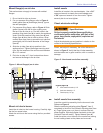
Dimension Z has been set per the ‘Set Z
Dimension’ instructions detailed earlier in this
manual. The acorn nut (Figure 7, item C) should
never be loosened once the Z dimension is initially
set.
Fuel supply line is correctly installed, the oil tank is
suffi ciently fi lled, and shut-off valves are open.
Burner is securely mounted in appliance, with
pressure fi ring plate and gasket installed for
pressurized chamber application.
Appliance has been fi lled with water (boilers) and
controls have been operationally checked.
Burner has been installed in accordance with
appliance manufacturer’s instructions (when
available).
Also refer to appliance manufacturer’s instructions
(when available) for start-up procedures.
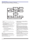
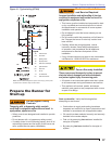
Initial head position (Figure 7)
The indicator plate assembly markings
correspond to head position settings.
Loosen the fastener (Figure 7, item d) and
slide the indicator plate until the number on the
indicator plate corresponds to the initial head
setting listed in Table 7, for the desired fi ring
rate.
When the head position has been set, tighten
the fastener and the spline nut.
□
□
□
□
□
□
□
□
○
○
○
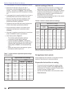
Table 8 - Initial air shutter and band settings
Rate
GPH
Approximate air settings
CF500
CF800
Tube A Tube B
Shutter Band Shutter Band Shutter Band
1.75 1 0 -- -- -- --
2.25 2 0 -- -- -- --
3.00 10 1 1 0 -- --
3.50 10 2 3 0 -- --
4.00 10 3 4 0 -- --
5.00 10 5 9 0 8 2
5.50 10 10 9 5 9 4
6.00 -- -- 10 3 10 3
7.00 -- -- 10 8 10 5
8.00 -- -- -- -- 10 10
Note: These settings are appoximate, and can vary depending on
actual job conditions and overfi re pressure
Table 7 - Initial indicator adjustment plate settings
(head position)
Rate GPH
Approximate head settings
CF500
CF800
Tube A Tube B
1.75 0 -- --
2.25 0
3.00 4 0 --
3.50 5 1 --
4.00 5 2 --
5.00 6 4 3
5.50 6 4 4
6.00 -- 4 4
7.00 -- 6 5
8.00 -- -- 6
Initial air settings (Table 8)
Loosen the air band and shutter, and adjust to the
approximate fi ring rate settings given in Table 8.
These initial settings should be adequate for starting
the burner. Once the burner is in operation, the air
settings will be adjusted for best performance as
discussed later in this manual.
Follow the procedures described later in this manual
for fi ne-tuning the air settings.
○
○
○
Set appliance limit controls
Set the appliance limit controls in accordance with the
appliance manufacturer’s recommendations.
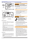
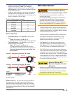
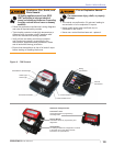
Prepare the fuel unit for air venting
To vent air from the oil supply line, attach a clear
hose to the pump air bleed valve (Figures 8 & 9)
on the fuel unit. Provide a container to catch the oil.
Loosen the pump air bleed valve.
Vent the air as described in the next section under
Start the burner.
○
○
Section: Prepare the Burner for Start-up